Environmental Engineering Reference
In-Depth Information
Syngas
High Temperature
Air
Solid Waste
Waste Material
Fixed grate
Syngas
Slag
High Temperature
Air
FIGURE 6.3
A schematic diagram of twin chamber “bed type” g
asifier.
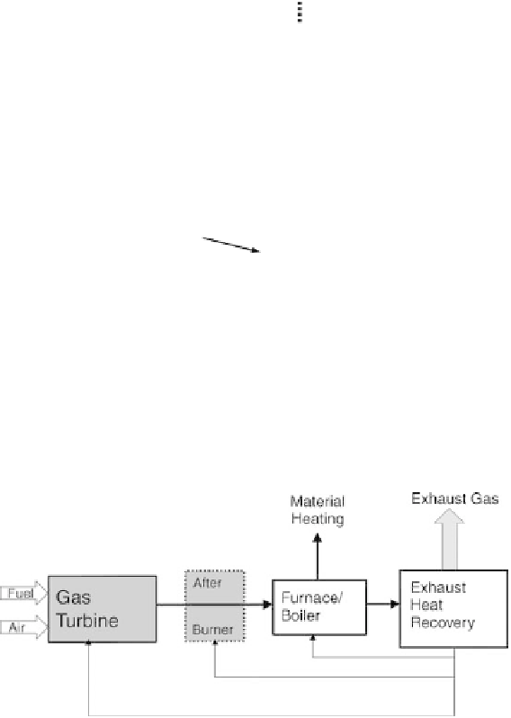
FIGURE 6.4
A schematic diagram of industrial g
as turbine and furnace.
produced; see
Figure 6.6
.
Of course, this is an ideal representation for a plant with
the aim to stimulate and challenge engineers on the design of future facilities.
Much of what has been discussed so far involves the transformation of waste to
syngas chemical energy in only one stage in the bed. A gasifying agent can be used
to improve the calorific value of the gas produced. One such agent includes steam
but another suitable gas can also be used. A schematic diagram of the steam-assisted
gasification system is shown in
Figure 6.7
.
The objective of the gasifying material
is to further enhance the conversion of carbon in the waste (fuel) to syngas fuel.
The syngas evolved can also be used for power generation, using, for example, high
temperature air principles in micro gas turbines. Typical mole fraction of the steam
in air in Figure 6.7 would be 10 to 20%, depending on the properties of the fuel.


Search WWH ::

Custom Search