Environmental Engineering Reference
In-Depth Information
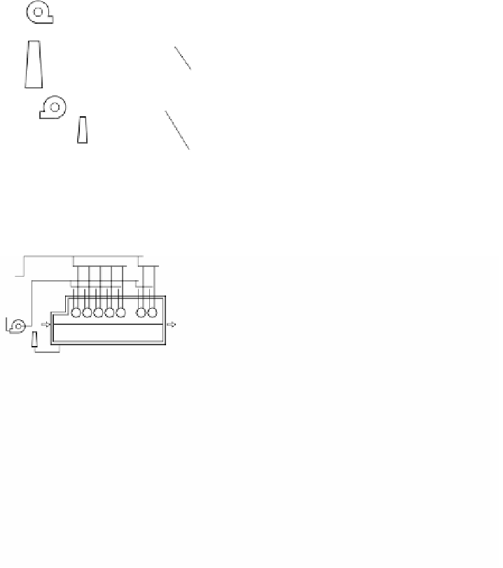
Combustion air
Exhaust gas 1
Thermal storage media
Steel
discharging
side
Steel
charging side
1
Non-combustion zone
2
Preheating zone
3
Heating zone
4
Soaking zone
Skids
Exhaust gas 2
FIGURE 5.27
Continuous reheating furnace for semifinished steel with regenerative heat
exchangers.
B
B
B
B
B
B
B
B
B
B
B
B
B
B
B
B
B
B
B
B
B
B
B
B
B
B
B
B
(C) Air/gas flow system
(A) Air/gas flow system
1400
1400
1200
1200
1000
1000
800
800
600
600
Upper furnace temperature
Top surface
Center
Backside surface
Upper furnace temperature
Top surface
Center
Backside surface
400
400
200
200
0
0
0
10
20
30
0
10
20
30
40
Furnace length, m
Furnace length, m
(B) Distribution of temperature of steel
(D) Distribution of temperature of steel
FIGURE 5.28
Distributions of temperature of steel in a conventional furnace (C, D) and a
high performance furnace (A, B) with air/gas flow systems.
For the basic functions of the simulator, it was also decided that the simulator
would be a process simulator for studying such characteristics of a reheating furnace
as fuel consumption and required furnace length. It was then necessary to obtain
the temperature of steel in the furnace and to observe the effects of varying other
parameters. For calculation method and input data, the simulator is a simplified
model and basic data are input to carry out the calculations. The furnace size, zone
length, furnace height, and furnace width serve as one factor. The simulator calcu-
lates the heat balance (
Figure 5.29
)
and the following are input as operational
conditions required for the calculation:


Search WWH ::

Custom Search