Environmental Engineering Reference
In-Depth Information
T
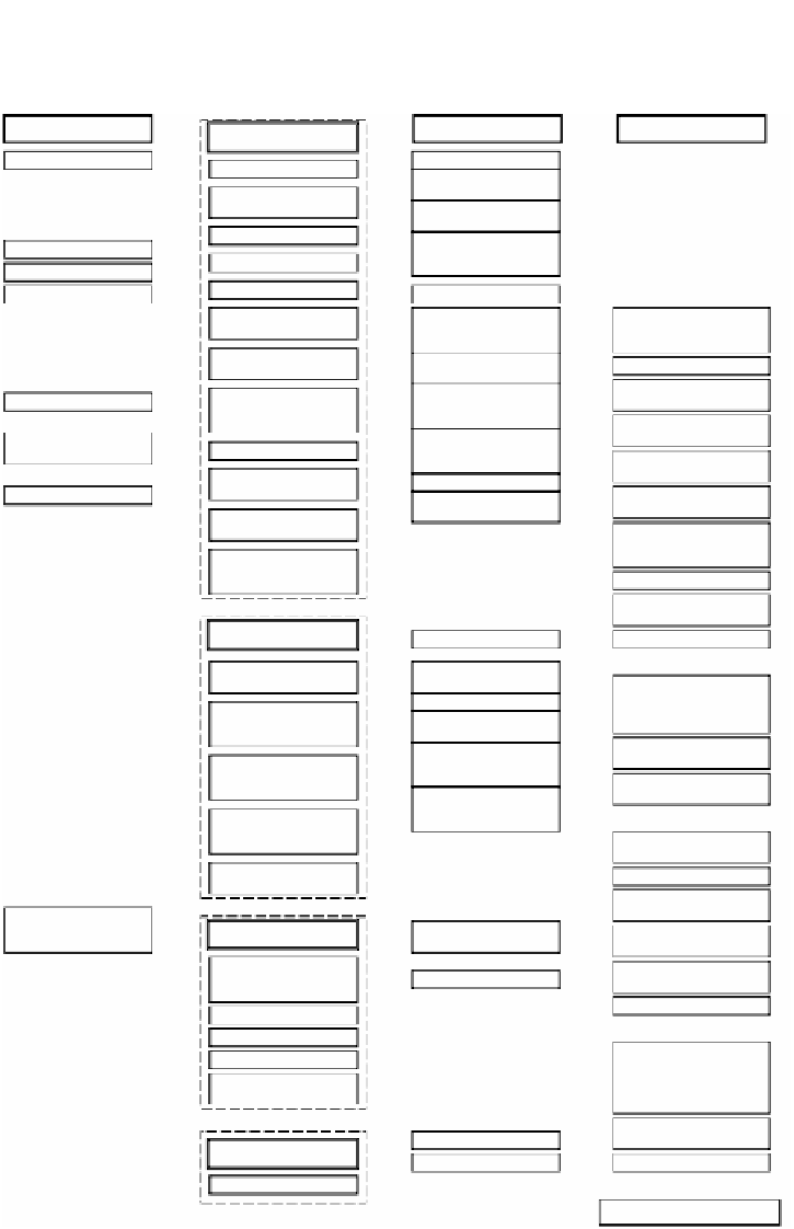
ABLE 5.2
High Performance Furnace Design Flow
Database
Restrictions
Basic design
Optimum shape of furnace
In-furnace width database
Heating capacity ton/h
Furnace width
Shape of object to be
heated
Charging and discharging
temperatures
Arrangement of support
beams
Furnace length
Soaking level (Temperature
distribution on discharged
sample)
Product mix
Furnace bed load database
In-furnace height database
Effective furnace length
Furnace height
Maintainability
Positions of furnace and
equipment placed in front of
and behind the furnace
Treatment method of
exhaust gas of combustion
Energy saving measures
and downsizing of furnace
and peripheral equipment
In-furnace transportation
system (hydraulic system,
electric motor system)
Permissible skid mark
Position of outlet and
direction of exhaust
Configuration of refractory
material in the furnace body
In-furnace heat transfer
calculation
Basic design plan 1
Standard material and product
mix ton/h
Determination of furnace type
Provisional determination of
furnace bed load
Provisional determination of
heat pattern
Consideration of emissivity of
object to be heated
Determination of effective
furnace length
Determination of furnace
dimensions (length, width and
height)
Determination of zone division
Determination of type and
layout of burners
Selection of optimum regenerator
CG
and preheated air
temperature database
Shape, dimensions, and
material of support beam
button
Skid mark database
Outer wall heat release
database
W.B. mechanism
Shape and dimensions of
inlet and outlet
Position of outlet and
direction of exhaust
Heat balance database
Scale treatment method on
furnace bed and water-
seal trough
Suitable burner
Type of fuel
In-furnace heat transfer
calculation
Temperature distribution in
furnace-width direction
NOx regulations
Components of combustion
gas (CO/CO
2
, H
2
/H
2
O)
Inspection for harmful
substances (CO, SOx,
smoke and soot)
Maximum and minimum
combustion rate of burner
and shape of flame
Basic design plan 2
Integration of heat balance in
each zone and confirmation
of results
Estimation of the flow of in-
furnace gas and in-furnace
temperature distribution
Determination of type,
number, capacity of burners
Determination of capacity
and number of burners in
each zone
Determination of combustion
rate in each zone
Grouping of burners in each
zone and grouping of
piping
Selection of optimum
regenerator
Basic design plan 3
Determination of blower capacity
Determination of exhaust fan
Determination of smoke stack
draught (diameter, height)
Pressure control database
Temperature control
database
Selection of temperature
control level
Control system
Determination of fuel unit
consumption
Determination of cooling water
quantity
Confirmation of types of utilities
Determination of burner
turndown ratio and c.v.
diameter
Furnace pressure control
Limit of air penetration
O
2
control
Instrumentation plan
Flow rate control
Exhaust gas temperature
control at regenerator outlet
Preparation of control diagram
(Power, heat transfer, tempera-
ture control, flow rate control,
pressure control, safety device)
Preparation of utility system
diagram
Safety standard
Emergency measures
Safety measures
Preparation of operation plan
Combustion safety device
High performance furnace


Search WWH ::

Custom Search