Environmental Engineering Reference
In-Depth Information
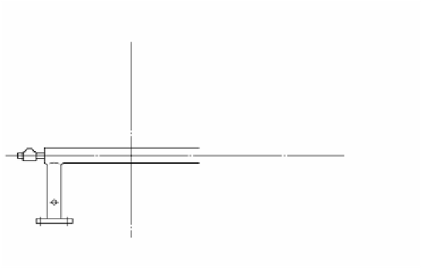
Combustion air
Burner tile
Gas
FIGURE 4.20
Structure of conventional burner.
Gas
Primary air
Regenerator
Secondary air
Type A burner
Primary gas
Secondary air
Primary air
Waste gas
Gas
Secondary gas
Regenerator
Combustion air
Waste gas
Type B burner
Type C burner
FIGURE 4.21
Structure of diluted and high temperature air combustion burner.
The diluted and high temperature air combustion burner has no burner tile to
hold the flame and has a longer feeding distance between fuel and combustion. Its
structure may appear to make it impossible to maintain a steady flame in the
conventional combustion concept. However, it is considered that steady combustion
can be maintained even in this structure by the use of high temperature air well
beyond the conventional range of combustion, and that slow combustion is realized
by suppression of the rapid combustion reaction, which otherwise occurs as the
result of an introduction of high temperature air.


Search WWH ::

Custom Search