Environmental Engineering Reference
In-Depth Information
combustion type burner method.
Figure 2.82
shows the test furnace.
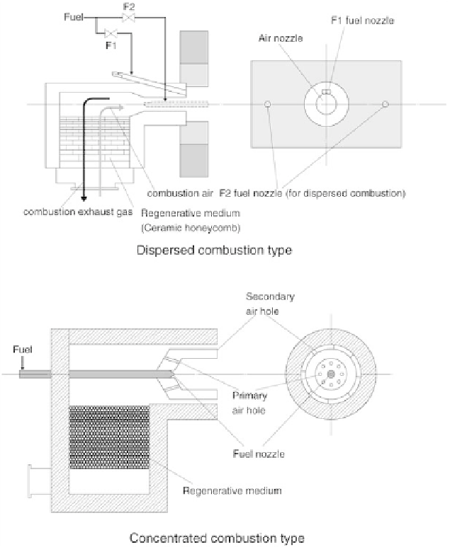
Figure 2.83
shows the burners.
Figure 2.84
shows the conditions of flame combustion.
Figure
2.87
s
how the in-furnace temperature distribution.
Figure 2.88
shows the in-furnace
heat flux distribution.
FIGURE 2.83
Outline of test burners.
1. Outline of combustion test furnace (see
Figure 2.82
)
2. Outline of test burners (see
Figure 2.83
)
3. Flame pictures with different types of fuels (see
Figure 2.84
)
5. In-furnace temperature distribution (see
Figures 2.86
and
2.87
)
6. In-furnace heat-flux distribution (see
Figure 2.88
)
Search WWH ::

Custom Search