Civil Engineering Reference
In-Depth Information
N
Load
transducer
Metal head block
Strain 1 (4)
Terminal
stud
Conductive
adhesive tape
Strain 2 (5)
Strain 3 (6)
Ground
terminal
Rubber
joint
AC
adaptor
Support
AC
adaptor
Power on/
off button
Constant
resistance
IMC data acquisition
system
AC voltage selector
4.5
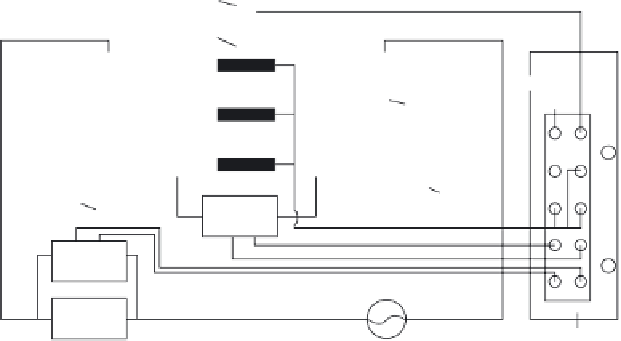
Arrangement of measuring points.
Six strain gauges were applied for measuring the longitudinal strain, two
of which (Strain 2(5)) were used on each side of the two opposing surfaces
to measure the strain of initial geometrical neutral axis (IGNA) under the
externally applied load N.
During the loading process, the strain near the top of the concrete beam
in the compression zone, the strain of IGNA and the tensile strain near the
bottom of the beam were measured by strain gauges. The resistance of
concrete beam was measured simultaneously. The IGNA strains were then
obtained by strain gauges (2) and (5). The resistance of the beams was
continuously measured during loading by using the four-pole method
described above. Other experimental instruments included an AC stabilized
voltage supply, IMC Intelligence Data Collecting System, a fi xed resistor
and an AC/DC converter. A schematic view of the beam under loading with
current and voltage electrodes is illustrated in Fig. 4.5. Rubber joints were
placed under the support points
during the experiment (see Fig. 4.5) in
order to isolate the concrete beam from the loading frame.
4.3
Infl uence of conductive admixtures on the
mechanical properties of concrete
4.3.1 Infl uence on workability and compression strength
The workability of high fl owable fresh concrete, with and without conduc-
tive admixture, has been evaluated by measuring the slump fl ow. The experi-
mental results of workability are listed in Table 4.5. The factor
d
represents

Search WWH ::

Custom Search