Civil Engineering Reference
In-Depth Information
Below we introduce the generic fi ve-layer device technology in Section
11.2.1 and then survey some practical aspects of electrochromic glazings in
Section 11.2.2. The subsequent parts, Sections 11.2.3 and 11.2.4, discuss the
actual electrochromic fi lms and the transparent conductors needed for
applying the voltage, respectively. Finally Section 11.2.5 presents a case
study of a particular type of electrochromic device with potential for very
low-cost manufacturing.
11.2.1 Generic fi ve-layer 'battery-type' device design
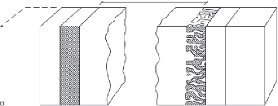
Figure 11.1 is a sketch of a standard electrochromic device (Granqvist,
1995) with fi ve superimposed layers on a single transparent substrate or
positioned between two such substrates. The optical functionality originates
in the electrochromic fi lm(s) which alter their optical absorption when ions
are inserted or extracted from a centrally positioned electrolyte. This trans-
port is easiest if the ions are small, in practice being protons (H
+
) or lithium
ions (Li
+
). The electrolyte can be liquid, solid inorganic or comprised of a
polymer. The ions are moved in an electrical fi eld between two transparent
electrical conductors, and the needed dc voltage is around 1-2 V. Except
for very small devices, external metallic electrical contacts ('bus bars') must
normally be put over at least part of the circumference of the device in
order to achieve a reasonably fast and uniform colouring and bleaching.
+
+
+
-
-
-
+
-
+
+
-
-
+
+
+
-
-
-
lons
+
-
11.1
General electrochromic device design. Arrows signify ionic
movement in an applied electric fi eld. From Granqvist (1995).


Search WWH ::

Custom Search