Civil Engineering Reference
In-Depth Information
Vacuum pump
Deposition
chamber
Substrate
Nozzle
Film
Transfer pipe
Evaporation pipe
Evaporation
chamber
Tungsten oxidation
Induction heating
generator
Tungsten pellet
Pedestal
Synthetic air
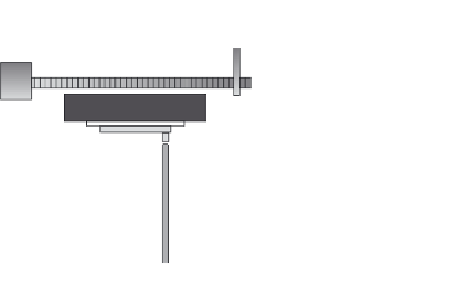
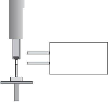
8.11
Schematic image of a unit for advanced gas deposition arranged
for making tungsten oxide nanoparticles. From Reyes
et al.
(2004).
now used to mass-produce nanoparticles that can be collected for later use
or for coating directly onto substrates. The technique and its implementa-
tion are described in detail in a topic by Hayashi
et al.
(1997).
Figure 8.11 illustrates an AGD unit; as shown, it is arranged for tungsten
oxide nanoparticle production (Reyes
et al.
, 2004) but the technique can be
used reactively or non-reactively to make nanoparticles of a large variety
of pure metals, oxides, nitrides, etc. Evaporation takes place in the lower
chamber into a laminar gas fl ow surrounding the vapour source. The vapor-
ized species are then cooled via collisions with gas molecules so that they
form tiny nuclei that subsequently grow in the gas fl ow. A thin transfer pipe
collects nanoparticles in a region at a controlled distance from the vapour
source and transports them in a gas stream that ends in the upper deposi-
tion chamber, which is maintained at good vacuum. A separate evacuation


Search WWH ::

Custom Search