Graphics Reference
In-Depth Information
3.
Use the values for the x- and z-axes as the dimension on a plane (a cube with no y dimension) created
in a new layer. When placed at the origin, the boundaries of this square will fall directly in the middle
of the border tiles.
4.
Apply a new material (M key) to the plane.
5.
In the Shader Tree, add a new image to the plane material. Set the size to 1024×1024 pixels.
6.
Change the image layer effect to Displacement (Surface Shading
⇒
Displacement).
7.
Make sure that the plane mesh layer is selected and the tiles are in the background.
8.
Right-click the blank image layer and choose Bake From Object To Texture.
9.
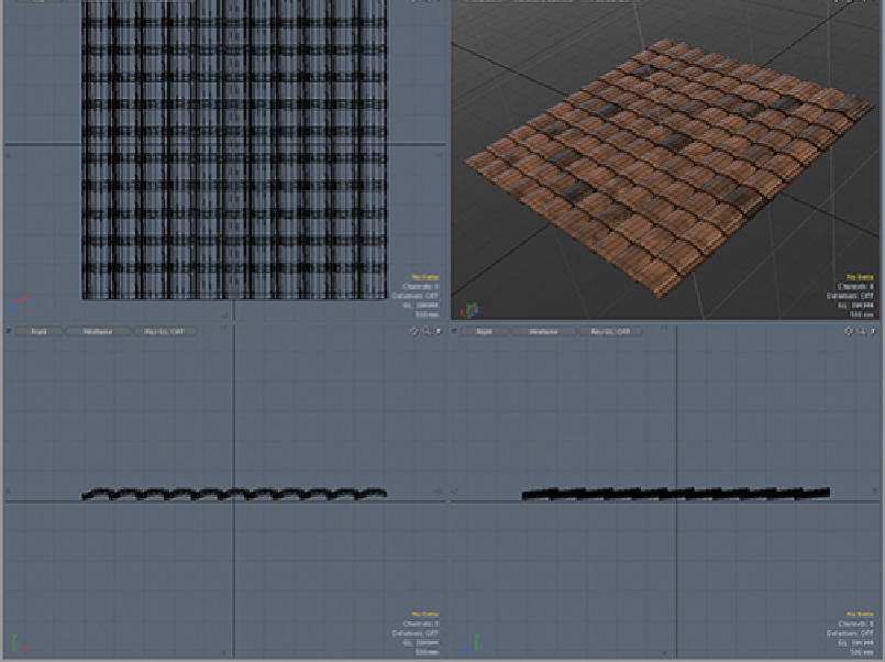
The pop-up menu asks you to enter a distance. This is the maximum distance that a ray can travel to
track the displacement. Look in the side view to see how far away the tiles are from the plane at their
peak and enter a value slightly higher in this field. For this example, I used a distance of 275 mm.
10.
After the image has baked, select it in the Shader Tree and choose Save Image from the File menu.
11.
In the image texture properties, set the Low Value to -100% and High to 100%.
12.
Set the Displacement Distance for the material on the plane to the same depth as the distance used
to bake the displacement image itself.
13.
Turn on Double Sided for the material. This will make the tiles visible from the underside.
This same process can be used to create bump and normal maps. When applied, the resulting plane will
look like
Figure 10-25
. Please note that the displacement will not appear in real time unless the plane is in
PSubs.