Graphics Reference
In-Depth Information
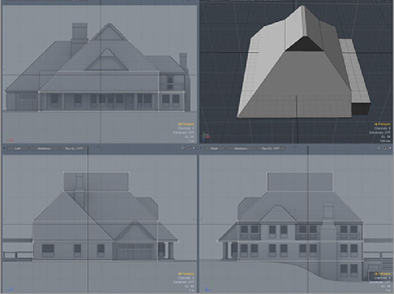
The second section of the roof was created with a large basic cube that overlaps the actual shape. Once
the slope of the roof is defined on the cut-off side, a slice can be added to separate the excess geometry. De-
lete the extra geometry and use the Bridge tool to fill in the open section.
Figure 10-5
shows the secondary
section of the structure.
Fill in the remaining sections with individual chunks of simple geometry, as shown in
Figure 10-6
.
Again,
simple cubes with a bevel and a few adjusted points will create the building blocks for the full form. The
assembled model is shown in
Figure 10-7
.
These basic geometric forms will be the basis for the finished model and will be very helpful for creating
the full model in the next section.
Figure 10-5:
Cutting off sections of simple geometry can produce more complex forms easily.