Graphics Reference
In-Depth Information
1.
Select two polygons that run around the beam, where the edges are to be inserted.
2.
Enable the Loop Slice tool.
3.
Set the Count to 31 (this will result in 32 polygons dividing the surface).
4.
Click the Uniform button to place 31 evenly spaced slices around the beam.
This sets up the geometry for the creation of the arch. A simple combination of the Move tool and a
Cylinder falloff will create the curved surface. Creating the arch can now be done in a few simple steps:
1.
Select all of the edges on the underside of the beam.
2.
Choose the Cylinder falloff from the Falloff menu.
3.
Set the falloff Axis to Y.
4.
Set the Shape Preset to Ease-In.
5.
Turn on the Move tool (W).
6.
Move the selection up 450 mm.
7.
Press the Q key to drop the tool and Esc to clear the falloff (or select None from the Falloff menu).
The arch is now completed and should look like the image shown in
Figure 8-27
.
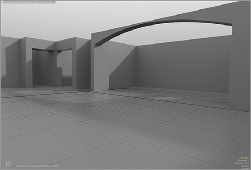
Repeat this procedure in any areas where you want a similar arch. Make sure that the falloff is on the
right axis (all of these will be either the z-axis or the x-axis) for each arch. With these completed, the main
structure is finished and should look like
Figure 8-28
.
Now the doors, windows, and architectural accents
can be added to complete the model.
Figure 8-27:
The kitchen arch completed
Figure 8-28:
Walls and floors are completed, and the model is ready for details to be added.