Environmental Engineering Reference
In-Depth Information
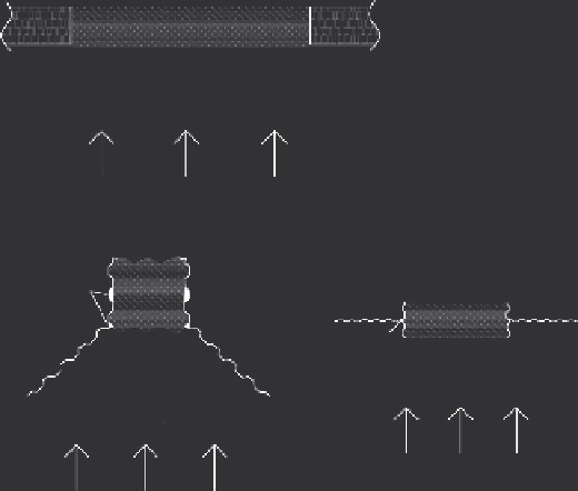
(a)
Natural ground
Permeable reactive material
Estimated capture zone
GW flow direction
(b)
Permeable reactive material
Permeable reactive material
Bentonite
Bentonite
Sheet piling
Sheet piling
Estimated capture zone
Estimated capture zone
GW flow direction
GW flow direction
FIGURE 1.4
PRB configuration: (a) continuous barrier and (b) “funnel-and-gate” system.
by large trees, recharge from nearby water body) is a vital step in the design
of a PRB system to ensure that the PRB is oriented perpendicular to the
flow so that it captures the maximum volume of groundwater (Puls, 2006).
Generally, the recommended approach is to conduct high-resolution site
characterization along with groundwater and solute transport modeling to
simulate possible case scenarios and design the orientation and dimensions
of the PRB.
The reactive material used for the construction of the permeable wall var-
ies with the type and concentrations of contaminants, the total mass of con-
taminants, and the groundwater composition (Table 1.2) (Birke et al., 2003;
Thangavadivel et al., 2013). Feasibility studies are crucial for the design of
PRB systems including choice of the reactive material, laboratory column
experiments, estimation of required residence time, and calculation of reac-
tive zone thickness (Roehl et al., 2005a). Since the first PRB trial in Canada
(Gillham and O'Hannesin, 1992, 1994), a range of different contaminant types
have been remediated using reactive materials that vary considerably in
their chemical composition (Table 1.2) and their interactions and mechanism
of contaminant removal. Zero-valent iron (ZVI) is the most common reac-
tive material that generates low redox potential in groundwater, resulting in
the precipitation and removal of both inorganic (metallic) and organic con-
taminants (Meza, 2009; Xenidis et al., 2002). Permeable reactive subsurface
Search WWH ::

Custom Search