Environmental Engineering Reference
In-Depth Information
ceased. It can also lead to redistribution of subsurface gas storage. Effective
pervasive gas propagation is in the range of 10
−2
-10
−1
m/h.
When applying HDI, local increases in, as well as the homogenization of,
gas saturation are induced in a near region with an ROI <3 m (Geistlinger,
2010). In this case, gases can be effectively supplied to the bottom zone of
an aquifer (which is of special interest in unconfined aquifers), and when a
density-driven plume propagation is under consideration (e.g., a dissolved
CHC plume). With increasing distance and due to gas viscosity and com-
pressibility characteristics, the HDI injection pressure transforms almost
completely into high gas propagation velocities in coherent channelized net-
works. There is no additional gas saturation effect of HDI at greater distances
from the injection point and the effective gas propagation of channelized
flow is of >1 × 10
0
m/h. A wide velocity range indicates the instability of this
transport behavior with a few dominating macroflow paths.
Figure 10.4 and Table 10.1 summarize the current knowledge of gas storage
and propagation phenomena during DGI into sediments in the groundwa-
ter zone. Assuming an injection area of 10
−2
m² for bench scale testing and
10
1
m² for field applications, observed injection pressures and gas propaga-
tion velocities during rate controlled field testing of NDI and HDI (Weber,
2007, Geistlinger, 2010 and Zittwitz et al., 2012) are very similar. The gas injec-
tion pressure difference due to the hydrostatic level typically increases dur-
ing NDI from <5 × 10
0
kPa to 3 × 10
1
kPa when the injection rate is increased
from 0.5 to 2.5 m³/h STP. This indicates a change to channelized flow and a
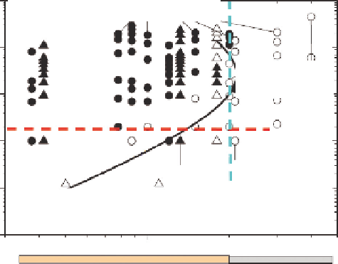
Channelized coherent flow
—
10,000
low/high-pressure injection: NDI/HDI
1000
100
Bubbly
incoherent flow
100
10
10
1
0.8/1.0
0.3/2
0.6/2
1.6/2
2.0/2.2
0.3/0.5
1
0.1
Pervasive incoherent flow
—
low pressure injection: NDI
0.1
0.5
1
2
3
4
Sand
Main grain size (mm)
Gravel
FIGURE 10.4
Gas flow classification scheme of bench to field-scale DGI. (Adapted from Geistlinger, H. et al.
2006:
Water Res. Research.
42, paper W07403, 12 p.; basic scheme and data from bench scale
test i ng.)
Search WWH ::

Custom Search