Environmental Engineering Reference
In-Depth Information
combined with its location independence, provide a storage technique with unique
characteristics. However, as well as cost, a number of areas need to be investigated
further in this area such as its design, power and storage capacities and environ-
mental impact to prove it is a viable option.
4.3 Compressed air energy storage
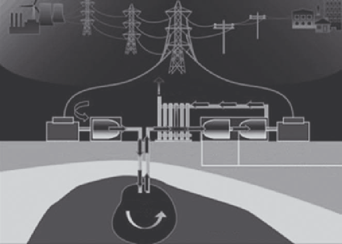
A CAES facility consists of a power train motor that drives a compressor (to com-
press the air into the cavern), high pressure turbine (HPT), a low pressure turbine
(LPT), and a generator (see Fig. 5).
In conventional gas turbines (GTs), 66% of the gas used is required to compress
the air at the time of generation. Therefore, CAES pre-compresses the air using
off-peak electrical power which is taken from the grid to drive a motor (rather than
using gas from the GT plant) and stores it in large storage reservoirs. When the GT
is producing electricity during peak hours, the compressed air is released from the
storage facility and used in the GT cycle. As a result, instead of using expensive
gas to compress the air, cheaper off-peak base-load electricity is used. However,
when the air is released from the cavern it must be mixed with a small amount of
gas before entering the turbine. If there was no gas added, the temperature and
pressure of the air would be problematic. If the pressure using air alone was high
enough to achieve a signifi cant power output, the temperature of the air would be
far too low for the materials and connections to tolerate [1]. The amount of gas
Exhaust
Waste Heat
Air
Recuperator
Compressor
LPT
Generator
Motor
HPT
Fuel (Natural Gas)
Compressed
Air
Salt Dome
Cavern
Figure 5: Compressed air energy storage facility [ 10 ].
Search WWH ::

Custom Search