Environmental Engineering Reference
In-Depth Information
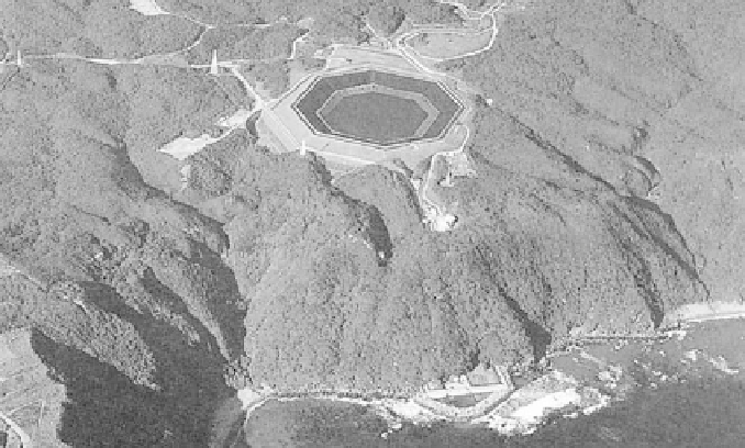
Figure 2: Pumped-hydroelectric storage facility using seawater at Okinawa,
Japan [ 6 ].
prevented by using paint and cathodic protection. A typical PHES facility has
300 m of hydraulic head (the vertical distance between the upper and lower reser-
voir). The power capacity (kW) is a function of the fl ow rate and the hydraulic head,
while the energy stored (kWh) is a function of the reservoir volume and hydrau-
lic head. To calculate the mass power output of a PHES facility, the following
relationship can be used [7]:
P
=
r
gQHn
(1)
where
P
C
is the power capacity in W,
r
the mass density of water in kg/m
3
,
g
the
acceleration due to gravity in m/s
2
,
Q
the discharge through the turbines in m
3
/s,
H
the effective head in m and
n
is the effi ciency.
Also, the storage capacity of the PHES may be evaluated with the following
equation [ 8 ]:
S
=
V
r
gHn
(2)
where
S
C
is the storage capacity in megawatt-hours (MWh) and
V
is the volume
of water that is drained and fi lled each day in m
3
. It is evident that the power and
storage capacities are both dependent on the head and the volume of the reservoirs.
However, facilities should be designed with the greatest hydraulic head possible
rather than largest upper reservoir possible. It is much cheaper to construct a facil-
ity with a large hydraulic head and small reservoirs, than to construct a facility
of equal capacity with a small hydraulic head and large reservoirs because: less
material needs to be removed to create the reservoirs required; smaller piping is
necessary, hence, smaller boreholes during drilling; the pump turbine is physically
smaller. Currently, there is over 90 GW in more than 240 PHES facilities in the
Search WWH ::

Custom Search