Environmental Engineering Reference
In-Depth Information
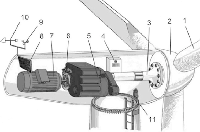
Figure 2: Sketch of a wind generating set [4]: 1, impeller blades; 2, hub; 3, main
shaft; 4, controller; 5, gearbox; 6, mechanical brake; 7, generator;
8, cooling system; 9, anemoscope; 10, wind vane; 11, yawing motor and
yawing bearing.
2.1 Gearbox
The gearbox is the bridge connecting the impeller and the generator. Since the
rotational speed of an impeller is between 20 and 30 rpm, and the rated speed of a
generating rotor is from 1500 to 3000 rpm or even higher, therefore a gearbox has
to be installed between the impeller and the generator to accelerate the low-speed
shaft. The running gearbox causes some power loss, most of which transfers into
heat and is absorbed by the lubricating oil and, thus, causes temperature rising in
the gearbox. If this temperature becomes too high, it will deteriorate the perfor-
mance of lubricating oil, causing lower viscosity and shorter drain period. More-
over, it also increases the possibility of damage to the lubricating fi lm under load
pressure, which leads to impairment of the gear meshing or the bearing surface
and, eventually, the equipment accident. Therefore, restriction of temperature rise
in the gearbox is a key prerequisite for its endurable and reliable operation [5].
On the other hand, in winter, when the ambient temperature is below 0°C, heating
measure for the lubricating oil in gearbox should also be taken into consideration
in order to avoid lubricating oil from failing to splash onto the bearing surface due
to high viscosity in low temperature, and, therefore, prevent impairment of the
bearing from short of lubrication. Normally, every large-scale wind turbine gear-
box contains a compelling cooling system and a heater for lubricating oil. How-
ever, in some regions where the temperature seldom drops below 0°C, such as the
coastal areas in Guangdong Province, China, heaters can be an exemption [6].
Search WWH ::

Custom Search