Environmental Engineering Reference
In-Depth Information
see Fig. 16. This type of model is typically used for the practical design of wind
turbine blades today.
The mid-thickness model
is also created from the geometry of the aerodynamic
shell. However, here the shell elements are located at the mid-plane for the different
parts of the cross section. The different material thicknesses in the cross section
imply that the FE shell will not have a continuous surface like the outer surface
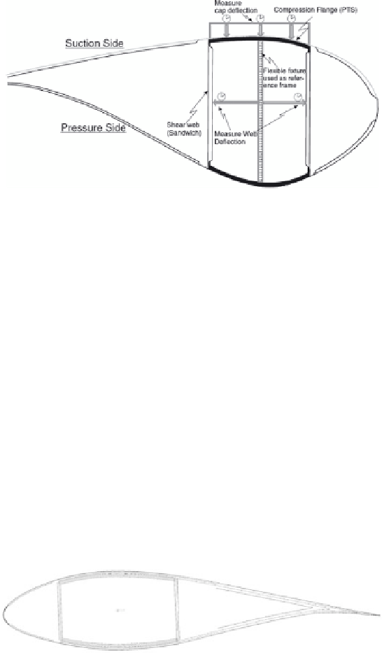
Figure 15: Measured relative defl ection of the box girder cap compared with linear
and non-linear FE analysis [8].
Figure 16: Outer surface shell FE model with material offset inwards from the
outer surface.

Search WWH ::

Custom Search