Environmental Engineering Reference
In-Depth Information
shown in Fig. 10 have an edge over the other tethered or moored systems be-
cause of the minimum need for submersible hull depth. Therefore, they could
be deployed in the shallower sites which could be just a bit too deep for the
seabed-mounted foundation concepts.
As offshore wind foundation, the TLP could achieve extra hull buoyancy by
increasing hull breadth instead off volume. It in turn enhances the lateral load
carrying capacity for the overall system. There are two challenges for the TLP
in offshore wind applications. Firstly, the overall hull-tendons-turbine system
must be designed as one integrated unit because of the coupling of the dynam-
ics. This makes the design process more complex. Secondly, the current wind
turbine designs require maximum angular deformation at the sea level to be
less than 1° to avoid imbalances in rotor loads. This deformation level may be
diffi cult to achieve without using more advanced high-tension-high-buoyancy
TLP, which could very well be the answer to the offshore wind developments
in deeper sites. Oscillation damper technology and advanced high-strength
tendon materials need to be evaluated to reduce the overall costs for this type
of TLP.
Spars
2.
: As shown in Fig. 11, spars rely on ballast weight at the spar keel for sta-
bility. The ballast is much stiffer than the tendons. Therefore their designs are
decoupled. Using spars in offshore wind may be problematic because their sta-
bility under lateral loads increases as the submersible length increases. There-
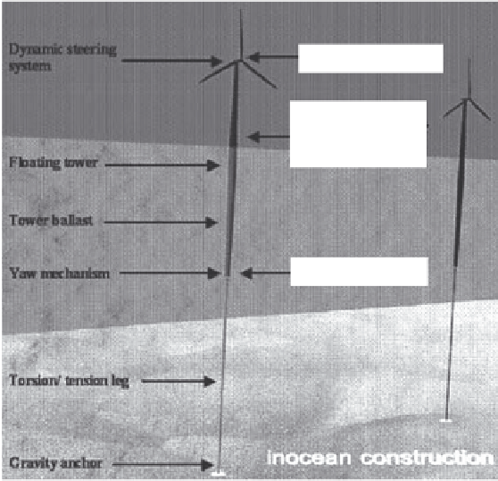
Dynamic
steering system
Downwind rotor
Aerodynamic
tower relative
to rotor
Floating tower
Tower ballast
Yaw mechanism
Joint bearings
Torsion/tension leg
Gravity anchor
Figure 11: SWAY concept with 640 ft tall spar fl oating buoy [ 16 ].

Search WWH ::

Custom Search