Environmental Engineering Reference
In-Depth Information
the separation disturbs the smoothly rotation of the rear wind rotor. Such rotational
speeds resultantly contribute the relative rotational speed
N
Topt
.
The maximum output
C
P
,
max
is larger with increment of
D
RF
and has the maxi-
mum value where
D
RF
is about 1.0, and
C
P
, max
of Tandem Wind Rotor GE com-
posed of the twisted blades is higher than that of Tandem Wind Rotor EE. As
recognized in Fig. 33, the maximum output coeffi cient
C
P
,
max
is affected mainly by
the output of the rear wind rotor
C
P
, maxR
.
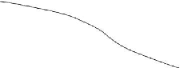
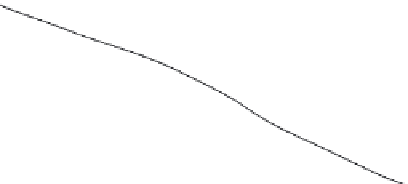
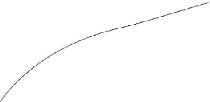
Figure 34 shows the rotational behaviours of the tandem wind rotors. The rota-
tional directions are changed drastically at about
D
RF
= 0.84, in the smaller
N
T
.
That is, the rear wind rotor rotates in the same direction as the front wind rotor,
while
D
RF
is less than 0.84. On the contrary, the front wind rotor rotates unfortu-
nately in the same direction as the rear wind rotor, while
D
RF
is more than 0.84.
Such rotational behaviour of the front wind rotor is not acceptable as for the
proposed intelligent wind power unit because the front wind rotor must keep the
rotational direction as expected in Chapter 3 (see Fig. 7).
The maximum output coeffi cient and the rotational behaviours against
D
RF
are
independent to the front blade profi les, as recognized in Figs 33 and 34. Therefore,
3000
Tandem Wind Rotor EE
V
= 10 m/s
L
= 0.08
N
F
2000
D
RF
=
1000
1.12
1.0
0.84
0.71
0.51
0
N
R
-1000
b
F
= 11 deg.
b
R
= 11 deg.
-2000
3000
Tandem Wind Rotor GE
N
F
b
F
= 10 deg.
b
R
= 16 deg.
2000
1000
D
RF
=
1.0
0
0.84
0.71
N
R
0.51
-1000
V
= 10 m/s
L
= 0.08
-2000
0
500
1000
1500
2000
2500
3000
3500
4000
N
T
min
-1
Figure 34: Effect of the diameter ratio on the rotational behaviours of the tandem
wind rotors.


Search WWH ::

Custom Search