Environmental Engineering Reference
In-Depth Information
rotor with the blade tip speed ratio
l
= 6 [=(blade tip speed)/(wind velocity)]. The
rear blade G is also formed with MEL002 and is twisted taking account of the fl ow
behind the front wind rotor. The front and the rear blade numbers are
Z
F
= 3,
Z
R
= 5
which are optimized in the previous paper [13]. Hereafter, the tandem wind rotors
are called “Tandem wind Rotor EE” which is composed of the front blade E and
the rear blade E, where the front and the rear blade setting angles are
b
F
=
b
R
= 11°
(see Fig. 28). “Tandem Wind Rotor GE” is composed of the front blade G and the
rear blade E, while
b
F
= 10°,
b
R
= 16°. “Tandem Wind Rotor GG” is composed of
the front blade G and the rear blade G, while
b
F
= 5°,
b
R
= 15°. “Single Wind Rotor
G” consists of with the front blade G, while
b
F
= 0°. These blade setting angles
were optimized at the preliminary experiments [14, 15].
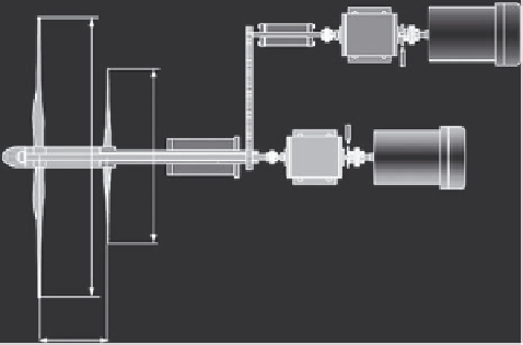
The model wind rotors shown in Fig. 32 were set perpendicular to the wind
direction, at 185 mm downstream of the wind tunnel outlet with the nozzle diam-
eter of 800 mm. The front and the rear wind rotors were connected directly and
respectively to the isolated motor with the inverter, in place of the peculiar generator.
The rotational torques of the front and the rear wind rotors were counter-balanced
by the rotational speed control. The performances of the model wind rotor in the
following discussions are evaluated without the mechanical torques of the bear-
ings and the pulley system. The fl ow conditions discharged from the wind tunnel
outlet, namely the inlet fl ow conditions of the wind rotors, are almost uniform and
axis-symmetry without the swirl.
The outputs of the model wind rotors may be smaller than those of the proto-
types, as the Reynolds number estimated at the front blade tip is (0.8-2.2)
10
5
in
×
the experiments.
6.2 Optimum diameter ratio of front and rear wind rotors
To know the optimum diameter ratio
D
RF
[=
d
R
/
d
F
], the performances of the tan-
dem wind rotors were investigated by changing the diameter of the rear wind rotor,
and are shown in Fig. 33. The output coeffi cient is defi ned by
C
P
=
P
/(
r AV
3
/2) and
(A)
(B)
(C)
(A): Torque meter
(B): Tachometer
(C): Motor
l
Figure 32: Model tandem wind rotors for performance experiment.


Search WWH ::

Custom Search