Environmental Engineering Reference
In-Depth Information
front wind rotor,
F
is the outlet fl ow angle determined by eqn (1) at each radial
position of the front blade. The angle
φ
F
may give the
outlet fl ow angle. Accordingly, the rotational torque of the rear wind rotor, namely
the angular momentum change, was determined with the simulated outlet fl ow angle
φ
F
is close to
φ
Fout
, that is,
φ
φ
Fout
of the front wind rotor, which is corresponding to the inlet fl ow angle of the rear
wind rotor, and the outlet fl ow angle of the rear wind rotor predicted by eqn (1).
Figure 22 also shows the designed rear blade with MEL012 aerofoil elements
[10], where the chord is also derived from eqn (2) but the height was determined
tentatively.
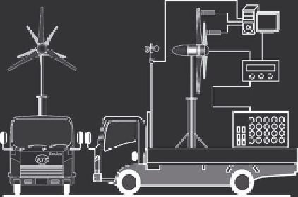
5.2 Preparation of the model unit and operations on the vehicle
The synchronous generator (Fig. 16) equipped with the tentative tandem wind
rotors (Fig. 22) were mounted on the circularly cylindrical tower as the down-
wind type, and boarded on the pick-up type truck as shown in Fig. 25. The wind
velocity can be controlled by the driving speed of the truck, and also measured
by the cup-type anemometer. The rotational speeds of the wind rotors, the output,
the induced voltage and the induced electric current were automatically accumu-
lated and stored in the personal computer every one second, in accompanying
with the data of the wind velocity. The output was consumed by many bulbs, but
these resistances depend mainly on the induced voltage, namely the rotational
speed, and the induced electric current affecting the temperature of the fi lament.
Therefore, the resistance was replaced by the specifi ed power of the bulb at 100 V,
P
, called “bulb load” as the indication for the external load.
The driving site is at the seashore of Wakamatsu, Kitakyushu, Japan, where there are
two straight roads of about 1.5 km in the north-south and the east-west directions. The
wind is calm and its direction is nearly constant, that is, the site is suitable for making
the experiments using the truck. The truck is used to be driven in three modes, which
are the acceleration, steady state, then the deceleration. Figure 26 shows one of the
rotational speeds of the front and the rear wind rotors
N
F
,
N
R
, and the wind velocity
V
Tachometer
Anemometer
Power meter
Bulb load
Figure 25: Field experiment on the pick-up type truck.


Search WWH ::

Custom Search