Environmental Engineering Reference
In-Depth Information
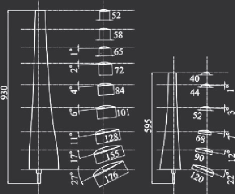
Front blade
Rear blade
Figure 22 : Blade profi les of the tandem wind rotors.
5.1.2 Rear blade design
The counter-rotational torque of the rear wind rotor must coincide with the rotational
torque of the front wind rotor designed above, but the convenient design procedures
for the rear blade interacting with the front wind rotor is not yet known. Accord-
ingly, the fl ow around the front wind rotor was simulated by the commercial CFD
code CFX-10 with
k
-
turbulent model, to get the inlet fl ow condition of the rear
wind rotor. In the simulation, the circularly cylindrical fi eld with 20
d
F
radius (
d
F
:
the diameter of the front wind rotor) was set, and was divided into two domains.
One is the rotational domain surrounding the wind rotor with 80,668 tetra-type ele-
ments (mesh size is 0.5 mm in close to the blade surface) and 6294 prism-type
elements in the radial direction with 2
d
F
, while 1
d
F
upstream and 3
d
F
downstream
of the rotor. The other is the stationary domain with 799,060 prism-type elements
surrounding the rotational domain, and both domains were joined with the Frozen-
Rotor interface keeping the relative blade position of the tandem wind rotors. The
fl ow around the tandem wind rotors with two-dimensional blades was simulated
in a trial by the above code and is shown in Fig. 23 accompanied with the plotted
experimental results, where
V
Mtm
and
V
θ tm
are the axial and the swirling velocity
components divided by the wind velocity
V
at the wind tunnel outlet,
R
is the dimen-
sionless radius divided by
d
F
/2,
Z
F
and
Z
R
are the blade numbers of the front and the
rear wind rotors, and the measurement sections M1-M3 and the blade profi le are
also given in the fi gure. It was confi rmed that the above code can predict roughly the
actual axial velocity, and the fl ow conditions are discussed in [13].
The fl ow around the front wind rotor equipped with three blades shown in Fig. 22
was simulated by the above code. Figure 24 shows the relative fl ow angles measured
from the tangential direction, where
f
Fin
and
f
Fout
are the simulated relative fl ow
angles averaged in the tangential directions at the inlet and the outlet sections of the
ε
Search WWH ::

Custom Search