Environmental Engineering Reference
In-Depth Information
in material properties such as thermal conductivity and specifi c heat capacity with
temperature.
6.4.5 Airgap stator design
In a conventional stator the radial and tangential forces act on the iron teeth, where
the stator conductors only see a small force due to leakage fl ux, but in an airgap
winding these forces act directly on the stator conductors. The stator coils not
only have to withstand these forces, but the forces also have to be transferred from
the coils using non-magnetic, non-conducting materials, since magnetic materials
would saturate leading to high losses due to AC fl ux, and high eddy current losses
would be induced in conducting materials.. These forces are also cyclic, so the
stator teeth are subject to high cycle fatigue loads. Even when the total generator
torque is steady, each individual coil side sees a force fl uctuating at 2
the sta-
tor fundamental frequency with a pattern rotating around the machine with the
rotor fi eld. In fault conditions the patterns are continually changing in time as well
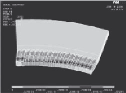
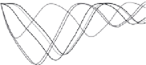
as space, involving complex mechanical time stepping modelling techniques. An
example of an electromagnetic and mechanical time stepping simulation of a short
circuit fault is shown in Fig. 16, where the graph show the force on individual sta-
tor teeth against time, with mechanical FE output of the defl ection. A number of
composite materials have been investigated, and some glass-based materials have
been found to offer acceptable properties.
The modelling produced a design with acceptable stress and defl ection using
composite material support structure. Further prototyping and fatigue testing is
planned.
The high power density that is possible with HTS machines also means that
careful design must be given to stator cooling. Due to the cost sensitive nature of
×
Stator mechanical model
during a short circuit
Tangential force on Teeth
Total Tangential Force in Slot
Total Tangential Force in Slot
50,000
50,000
F
o
r
c
e
0
0
-50,000
-50,000
slot 1
slot 2
slot 8
slot 13
slot 14
slot 18
slot 1
slot 2
slot 8
slot 13
slot 14
slot 18
-100,000
-100,000
-150,000
-150,000
-200,000
-200,000
-250,000
-250,000
Time
-300,000
-300,000
0
0
0.1
0.1
0.2
0.2
0.3
0.3
0.4
0.4
0.5
0.5
0.6
0.6
s
s
Figure 16 : Force and defl ection of stator coils.


Search WWH ::

Custom Search