Environmental Engineering Reference
In-Depth Information
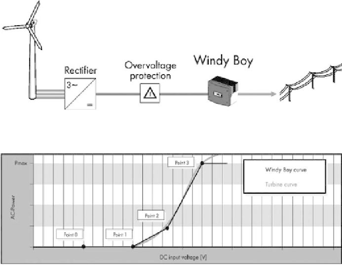
Figure 15: General arrangement of grid-tie inverter system (credit: SMA).
Figure 16: Grid-tie inverter programming (credit: SMA).
and an asynchronous generator are typically used (see below). Figure 15
shows the general arrangement for this approach. In this case three-phase
power (variable voltage and variable frequency) comes down the tower. It is
then rectified to DC, passes through an overvoltage protection relay and on
to the inverter.
The grid-tie inverter loads the turbine (i.e. extracts power) on the basis of volt-
age (i.e. turbine rpm). In this way the turbine can be operated at or near the point
of optimum system effi ciency all along the power curve, as illustrated in Fig. 16.
As the wind starts to rise, the DC voltage increases. As the voltage rises above
point 1, the inverter begins to load the turbine according to the line between points
1 and 2. As the voltage rises above point 2, the inverter begins to load the turbine
according to the line between points 2 and 3.
Above point 3 the rated power of the inverter is reached, and so regardless of
voltage (i.e. turbine rotational speed), the turbine is only loaded to that power. This
means that the turbine accelerates, since rotor power exceeds the power being
withdrawn by the generator. In this case the overspeed control system comes into
play, regulating the turbine rpm below a dangerous level. If the DC voltage rises to
a value that exceeds the input rating of the inverter (if, e.g. the overspeed control
mechanism fails), then the overvoltage circuit shown in Fig. 15 will disconnect the
turbine from the inverter input. Inverter effi ciency is poor at low power inputs, but
then typically rises to a high level.
Search WWH ::

Custom Search