Environmental Engineering Reference
In-Depth Information
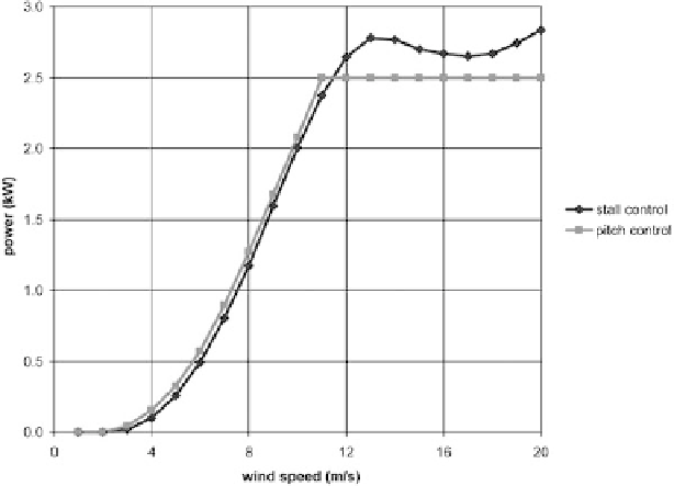
Figure 10: Typical power curves with stall and pitch control.
With the advent of grid-tie inverters, stall control is becoming less prevalent on
the smaller wind turbines, power curves are beginning to resemble that of the pitch
controlled turbine in Fig. 10, and power limitation accomplished in conjunction
with the rotor overspeed control (see discussion below). In this case a stalling rotor
design is no longer necessary.
It should be noted that it is diffi cult to get the same high aerodynamic effi ciency
on small turbines as on large turbines. This has to do with the formation of turbulent
boundary layer on the surface of the blade. Towards the leading edge of the blade
the boundary layer is laminar, but at some critical distance
l
across the blade surface
the fl ow becomes turbulent. This distance is a function of fl ow velocity (
V
), Reynolds
number (
Re
), viscosity (
m
) and density (
m
) as per the following equation:
l
=∗
(
e
m
) /(
V
∗
r
)
( 1)
This turbulence reduces pressure drag (the primary effect) and increases friction
drag (a secondary effect), with the net effect being a reduction in drag and an
improvement in rotor effi ciency. Small wind turbine blades have a small chord
length and therefore there is a relatively smaller region across the blade surface
where the fl ow is turbulent compared to large turbine blades, hence the higher
effi ciency from large turbine blades.
C
p
values on large turbines can be on the
order of 0.5, whereas on smaller turbines it is on the order of 0.4.
1.2.2 Rotor overspeed control
Turbines (e.g. gas turbines, steam turbines, wind turbines, etc.), when unloaded,
typically only have inertia to limit uncontrolled acceleration. Typically energy
Search WWH ::

Custom Search