Environmental Engineering Reference
In-Depth Information
winding is fed from the grid using voltage source converters. A rotor-side converter
is connected back-to-back with a grid side converter and requires only about 1/3 of
the overall turbine power rating to accomplish a wide range of output power control.
The system permits relatively fast response to signifi cant grid disturbances and
advantages for reactive power supply to the grid, power quality and improved har-
monics. Type C is a more expensive architecture than Type A or B designs, but it is
popular for its advantages.
Type D uses a synchronous generator that can have either a wound rotor or can be
excited using permanent magnets. This is also known as “full-power conversion”
and provides design and operational fl exibility including the option of eliminating
the gearbox. Variable speed operation is achieved by connecting the synchronous
generator to the grid through the frequency converter. Type D turbines are better than
Type C turbines despite the higher cost, as they are decoupled from the grid via
power electronics, resulting in excellent capability for power quality and reactive
power. Use of permanent magnets in the generator rotor offers the advantage of
greater effi ciency and high power density, resulting in more compact generators.
4.2.3 Governing dimensional considerations
One of the most important design drivers of a WT is the closest approach of the
blade tip to the tower. The baseline axial distance from the blade tip to the tower
wall for the fully unloaded blade in the 6 o'clock position is known as the “static
clearance.” The amount of clearance remaining for the actual turbine operational
conditions is a function of the loads imparted on the rotor blade and tower, the
blade geometry, stiffness, mass, and how the blades are positioned relative to the
rotor hub and the turbine [22]. Typical minimum operational blade-tower clear-
ance is 1/3 of the static clearance or a distance of one tower radius relative to the
tower diameter at the same elevation of the passing tip [59].
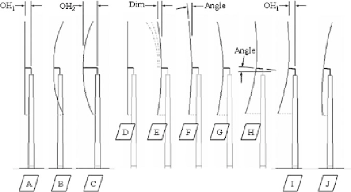
Blade-tower operational clearance considerations are shown in Fig. 10 relative
to the wind fl owing from the left to the right. Starting from the left, sketch /A/ is
Figure 10 : Blade-tower clearance for upwind facing WT.
Search WWH ::

Custom Search