Environmental Engineering Reference
In-Depth Information
A yaw system maintains the horizontal rotor axis pointing upstream into the wind.
A power conversion system that converts the low-speed rotational energy into
suitable shaft power to drive an electrical generator.
A tower and foundation structure to support the rotor and generator system at a
height that harvests the most amount of energy for an acceptable capital cost.
An electrical power distribution system that supplies the energy to the consumer
in compliance with local grid code and system requirements.
4.2.2 Mechanical
electrical power conversion architecture
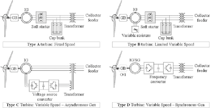
Figure 9 shows the four main types of WT architecture that have been employed
according to Wojszczyk
et al.
[21]. Types A and B are older and less prevalent
confi gurations, while Types C and D comprises the mainstay of modern MW
WT offerings.
Type A is the oldest and utilizes a squirrel cage induction generator (SCIG)
directly coupled to the electrical grid. It may incorporate a soft starter to limit in-
rush current during start-up conditions. The rotor is connected to the generator
through a gearbox and can often run at two different (but constant) speeds. This is
achieved by changing the number of poles of the stator winding. The generator
always consumes reactive power, and therefore this has to be compensated by
capacitor banks to optimize the power factor and maintain the voltage level.
Type B introduces a variable resistor in the rotor circuit of a wound rotor induction
generator (WRIG). This can be done using slip rings or the resistors and electronics
can be mounted within the rotor. The variable resistors control the rotor currents to
maintain constant power output and allow the WT to have dynamic response during
grid disturbances. Some degree of self-protective torque control and energy capture
range is provided by
−
10% speed variation.
Type C is known as the double fed induction generator (DFIG). It improves on the
Type B design by adding variable excitation (instead of resistance) to the rotor cir-
cuit. The generator stator winding is directly connected to the grid and the rotor
±
Figure 9 : The four main types of WT mechanical
−
electrical power conversion.
Search WWH ::

Custom Search