Environmental Engineering Reference
In-Depth Information
(a)
P
H
=421 kN
Deflection
y
(m)
Moment
M
(kNm)
Soil reaction (kN/m)
y
=1 m
-200000
20000
-500
0
500
-0.05
0.00
0.05
0.10
0
0
0
seabed
seabed
e
=26 m
5
5
5
water
10
10
y
= 60 mm
10
z
= 0
seabed
15
15
15
Stiff clay
c
u
=150 kPa
20
20
20
Steel pipe pile,
d
=1.3 m
25
25
25
z
= 23 m
(c)
(b)
1500
z
=22 m
γ′= 11.8 kN/m
3
c
u
= 150 kN/m
2
J
= 0.25
B
= 1.3 m
ε = 0.01
1000
12 m
1.5
500
β =3 (bending)
c
z
=0 m
1.45
0
β = 3 (deflection)
z
=0 m
a
1.4
-500
b
-1000
1.35
30
32
34
36
38
40
z
= 22 m
Steel wall thickness (mm)
-1500
-0.3
-0.1
0.1
0.3
y
(m)
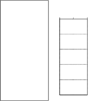
Figure 9.12
Multi-criteria reliability-based design of a laterally loaded pile in spatially autocorrelated clay: (a)
Numerical procedure for nonlinear
p
-
y
analysis of a steel tubular pile in a breasting dolphin; (b)
Matlock's nonlinear
p
-
y
curves; (c) combinations of pile external diameter and wall thickness for
reliability index
β
of 3.
at 26 m above the seabed can be inferred from statics once the deflection and rotation of
the pile at seabed level are known. The Matlock
p-y
curves for clays, as shown in
Figure
depth. The calculated pile deflection (
y
i
) at seabed level (where z = 0) is 0.0602 m. The pile
head deflection (at 26 m above the seabed) is, by integrating the moment-curvature equa-
tion, 0.994 m or about 1 m. Separate analysis using a specially written Fortran program to
perform the finite-element analysis using 60 equally spaced elements yielded a pile deflection
of 0.0596 m at seabed level, compared with 0.0602 m in
Figure 9.12
, and practically identi-
cal shear and moment distribution along the pile length.
For reliability analysis, the 23-m embedded length of the pile was discretized into 30 seg-
ments of progressively greater length. The random variables are the lateral load P
H
at pile


Search WWH ::

Custom Search