Environmental Engineering Reference
In-Depth Information
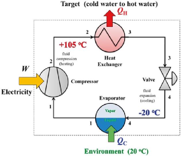
Fig. 5.4
Heat pump system that uses CO
2
as the working fluid for heating hot water. The com-
pressor pressurizes vapor CO
2
that increases its temperature. The heat exchanger allows the hot
CO
2
to transfers its heat to make hot water. The valve expands the CO
2
that causes cooling and
makes a vapor-liquid mixture form. The evaporator draws heat from the environment to vaporize
the liquid. Since the temperature of the CO
2
(− 20 °C) is much lower than that of the environment
(+ 20 °C), the heat pump can extract heat from the environment. The heat from the environment
is used to vaporize liquid CO
2
in the evaporator so that it can be compressed again in the cycle.
(Figure adapted from Smith et al.
2013
)
causes it to heat up. Then, after heat is transferred from CO
2
to water with a heat
exchanger, the CO
2
is depressurized through a valve to form a vapor-liquid mixture.
The depressurization of the CO
2
causes it to cool and is called a
Joule-Thomson
expansion
. Heat from the environment is used to vaporize the liquid formed so the
vapour can be recompressed for another cycle. The flow diagram shown in Fig.
5.4
is the basis for the Eco-Cute hot water heating system developed and marketed by
more than 20 different companies in Japan. As of 2013, more than 4 million units
have been installed.
The Eco-Cute system is a heat pump system that can be represented on a thermo-
dynamic temperature-entropy (
T
-
S
) diagram (Fig.
5.5
). For the case of pressuriza-
tion from 2 to 10 MPa shown by the path from
Point 1
to
Point 2
, the temperature
of CO
2
increases from − 20 °C (vapor) to 105 °C (supercritical). In Fig.
5.5
, the
compression of CO
2
is simplified as an ideal reversible process with no friction so
that ∆
S
of compression is taken to be zero. In actual compressors, some amount of
energy is lost by friction in the device and viscous losses by the fluid flow. Heat