Hardware Reference
In-Depth Information
the same power levels as servers did years ago, so rather than reinvent an incompatible connector,
the ATX12V 2.0 standard merely incorporated the 24-pin connector already specified in the SSI EPS
standard.
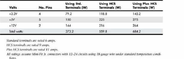
Compared to the previous 20-pin design, the 24-pin main power connector includes additional +3.3V,
+5V, and +12V terminals, allowing a substantially greater amount of power to be delivered to the
motherboard. Each terminal in the main power connector is rated to handle up to 6 amps of current.
By counting the number of terminals for each voltage level, you can calculate the power-handling
capability of the connector, as shown in
Table 18.11
.
Table 18.11. Maximum Power-Handling Capabilities of the 24-Pin Main Power Connector
This means the total power-handling capacity of this connector is 373 watts using standard terminals
or 560 watts using HCS terminals, which is substantially higher than the 251 watts available in the
previous 20-pin connector. Combining the 24-pin main and the 4-pin +12V power connector results
in up to 565 watts (standard terminals) or 824 watts (using HCS terminals) total power available to
the motherboard and processor! This is more than enough to support the most power-hungry
motherboards and processors on the market today.
CPU Power Connectors
Power for the processor comes from a device called the
voltage regulator module (VRM)
, which is
built into most modern motherboards. This device senses the CPU voltage requirements (usually via
sense pins on the processor) and calibrates itself to provide the proper voltage to run the CPU. The
design of a VRM enables it to run on either +5V or +12V for input power. Many have used +5V over
the years, but starting in 2000 most converted to +12V because of the lower current requirements at
that voltage. In addition, other devices might have already loaded the +5V, whereas only drive motors
typically used the +12V prior to 2000. Whether the VRM on your board uses +5V or +12V depends
on the particular motherboard or regulator design. Many modern voltage regulator ICs are designed to
run on anything from a +4V to a +36V input, so it is up to the motherboard designer as to how they
will be configured.
For example, I studied a system using a First International Computer (FIC) SD-11 motherboard,
which used a Semtech SC1144ABCSW voltage regulator. This board design uses the +5V to convert
to the lower voltage the CPU needs. Most motherboards use voltage regulator circuits controlled by
chips from Semtech (
www.semtech.com
) or Linear Technology (
www.linear.com
). You can visit
their sites for more data on these chips.
That motherboard accepted an Athlon 1GHz Cartridge version (Model 2), which according to AMD
has a maximum power draw of 65W and a nominal voltage requirement of 1.8V, and 65W at 1.8V
would equate to 36.1A of current at that voltage (volts × amps = watts). If the voltage regulator used