Hardware Reference
In-Depth Information
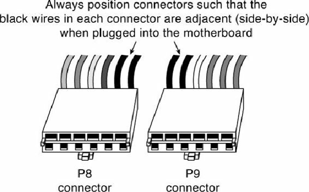
the two black wires (ground connections) on both power connectors are next to each other when
properly plugged in. Note the designations P8 and P9 are not fully standardized, although most use
those designations because that is what IBM stamped on the originals. Some power supplies have
them labeled as P1/P2 instead. Because these connectors usually have a clasp that prevents them from
being inserted backward on the motherboard's pins, the major concern is getting the two connectors
in the correct orientation side by side and also not offsetting by one or more pins side to side.
Following the black-to-black rule and ensuring they are on-center keeps you safe. You must take care
to ensure that no remaining unconnected motherboard pins exist between or on either side of the two
connectors after you install them. A properly installed connector connects to and covers every
motherboard power pin. If any power pins are showing on either side of or between the connectors,
the entire connector assembly is installed incorrectly, which can result in catastrophic failure for the
motherboard and everything plugged into it at the time of power-up.
Figure 18.20
shows the P8 and
P9 connectors (sometimes also called P1/P2) in their proper orientation when connected to a
motherboard.
Figure 18.20. The P8/P9 power connectors (sometimes also called P1/P2) that connect an
AT/LPX power supply to the motherboard.
Table 18.4
shows typical AT/LPX power supply connections.
Table 18.4. AT/LPX Power Supply Connectors (Wire End View)