Hardware Reference
In-Depth Information
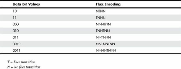
transitions for a particular bit sequence are designed to ensure that flux transitions do not occur too
closely together or too far apart.
Table 8.3. RLL 2,7 Data-to-Flux Transition Encoding
Limiting how close two flux transitions can be is necessary because of the fixed resolution
capabilities of the head and storage medium. Limiting how far apart two flux transitions can be
ensures that the clocks in the devices remain in sync.
In studying
Table 8.3
, you might think that encoding a byte value such as 00000001b would be
impossible because no combinations of data bit groups fit this byte. Encoding this type of byte is not a
problem, however, because the controller does not transmit individual bytes; instead, the controller
sends whole sectors, making encoding such a byte possible by including some of the bits in the
following byte. The only real problem occurs in the last byte of a sector if additional bits are
necessary to complete the final group sequence. In these cases, the endec in the controller adds excess
bits to the end of the last byte. These excess bits are then truncated during any reads so the controller
always decodes the last byte correctly.
Encoding Scheme Comparisons
Figure 8.10
shows an example of the waveform written to store the ASCII character X on a hard disk
drive by using three encoding schemes.
In each of these encoding scheme examples, the top line shows the individual data bits (01011000b,
for example) in their bit cells separated in time by the clock signal, which is shown as a period (.).
Below that line is the actual write waveform, showing the positive and negative voltages as well as
head voltage transitions that result in the recording of flux transitions. The bottom line shows the
transition cells, with T representing a transition cell that contains a flux transition and N representing
a transition cell that is empty.
The FM encoding example shown in
Figure 8.10
is easy to explain. Each bit cell has two transition
cells: one for the clock information and one for the data. All the clock transition cells contain flux
transitions, and the data transition cells contain a flux transition only if the data is a 1 bit. No
transition is present when the data is a 0 bit. Starting from the left, the first data bit is 0, which
decodes as a flux transition pattern of TN. The next bit is a 1, which decodes as TT. The next bit is 0,
which decodes as TN, and so on.
The MFM encoding scheme also has clock and data transition cells for each data bit to be recorded.
As you can see, however, the clock transition cells carry a flux transition only when a 0 bit is stored
after another 0 bit. Starting from the left, the first bit is a 0, and the preceding bit is unknown (assume