Hardware Reference
In-Depth Information
Using the multiple individual connectors shown in the previous figure, you would have to plug each
connector into the proper pin. Some internal chassis USB cables use two 5-pin inline connectors, in
which case you just need to ensure that you don't put them on backward. Consult your motherboard
and chassis manual for more information if you are unsure about your particular connections.
Caution
If your chassis uses multiple individual nonkeyed connections for USB 1.1/2.0 header cables,
you must be sure to connect them properly to the connector on the motherboard. If you connect
them improperly, you can cause a short circuit to occur that can damage the motherboard or any
USB peripherals you plug into the front panel connectors. Higher-quality motherboards usually
have self-healing fuses on the power signals, which can prevent damage if such a situation
occurs.
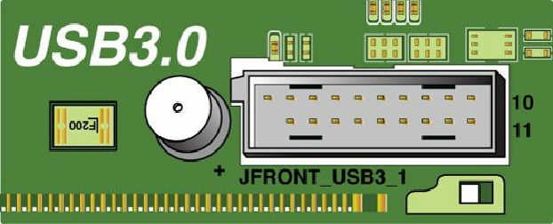
4.37
shows a typical USB 3.0 motherboard header.
Figure 4.37. A typical USB 3.0 motherboard header uses a 19-pin connector.
Table 4.42
lists the pinout for a standard USB 3.0 motherboard header.
Table 4.42. USB 3.0 Header Connector Pinout