Hardware Reference
In-Depth Information
case (see
Figure 4.10
)
. Obviously, if you have a smaller case designed for MicroBTX or picoBTX,
you won't be able to put the larger microBTX or BTX boards there.
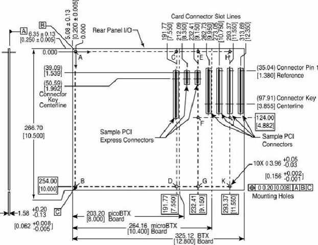
Figure 4.10. BTX specification 1.0a motherboard dimensions.
BTX requires up to 10 mounting holes and supports up to seven slots, depending on the size, as
Table 4.2. BTX Motherboard Mounting Holes
BTX also clearly specifies volumetric zones around the motherboard to prevent interference from the
chassis or internal components such as drives, which allows for maximum interchangeability without
physical interference or fit problems.
With processors exceeding 100W in thermal output, as well as voltage regulators, motherboard
chipsets, and video cards adding to the thermal load in a system, BTX was designed to allow all the
high-heat-producing core components to be mounted inline from front to back, so that a single high-
efficiency thermal module (heatsink) can cool the system. This eliminates the need for an excessive
number of fans. The thermal module includes a heatsink for the processor, a high-efficiency fan, and a
duct to direct airflow through the system. Extra support for the thermal module is provided under the
board via an SRM, which provides structural support for heatsinks that are much heavier than
allowed in ATX designs (see
Figure 4.11
)
.