Hardware Reference
In-Depth Information
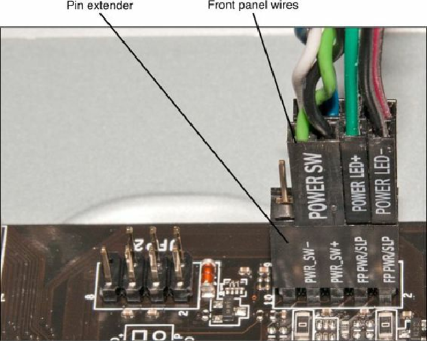
Figure 19.28. Front panel connectors plugged into a pin extender. The pin extender fits between
the front panel headers on the motherboard and the front panel connectors.
Note
A pin extender (shown in
Figure 19.28
) enables you to connect front-panel wires such as
power, reset, and LED to a single connection that you can plug into the motherboard. This
helps avoid miss-wiring because the pin extender is keyed to prevent incorrect installation.
Installing the Drives
At this point, you should install your hard drive(s), solid-state drives, optical drive(s), and optional
floppy drive.
Drive Configuration
Before you physically install a drive in the computer, you must ensure that it is properly configured.
Serial ATA drives generally don't require a jumper configuration. Parallel ATA drives, on the other
hand, require that each drive be configured as either master/slave or cable select (CS). Normally, you
would set Parallel ATA hard drives to CS and use an 80-conductor cable.
To learn more about configuring PATA drives, see the
Chapter 7
section, “
ATA Standards
,”
p.
380
.
Because Serial ATA drives connect to the SATA host adapter in a point-to-point configuration using
a dedicated cable, there is no master, slave, or cable select setting as there is with Parallel ATA
drives. Note, however, that some SATA hard disk drives might have jumpers to help solve
compatibility issues, such as to configure a newer 6Gbps interface speed drive into the slower 1.5 or