Image Processing Reference
In-Depth Information
58
Chapter 5
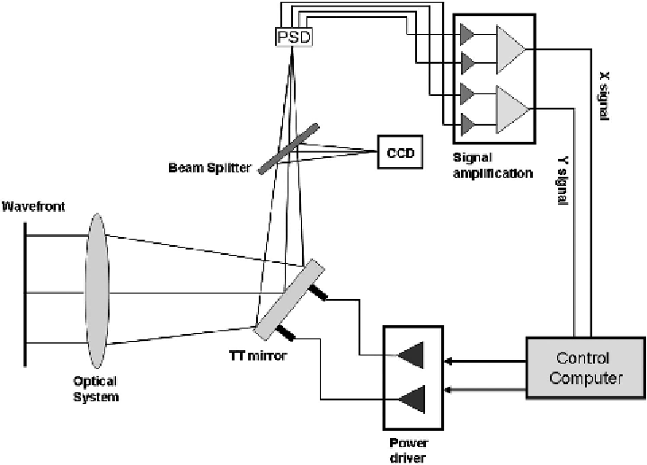
Figure 5.8
Schematic of the optical system and control system layout.
mirror. Again, many commercial input-output devices are available to integrate the
signals and the computer. Since this system operates at low speed, these devices are
both simple to use and inexpensive to obtain. Several input-output signal interfaces
use the universal serial bus (USB) ports of computers, providing a convenient sin-
gle interface for software development. This is illustrated in Fig. 5.8.
Once the signals can be read into the computer from the discrete devices used in
the system, the actual control software can drive the system. The system control re-
quirements can now be defined. Here, the control system is kept very simple, con-
fined to biasing the system for normal operation, configuring the range of motion of
the devices, and driving the mirror in set patterns while monitoring the position us-
ing the PSD. This system is developed to operate at a bandwidth of just a few hertz.
5.5 Information Flow for Image Stabilization
The image quality resulting from an image-stabilization system ultimately depends on
the software used to control the system. There is no single best way to control the mir-
ror based on the information from the optical sensor, and many schemes are in use.
The basic information flow diagram for image stabilization is shown in
Fig. 5.9, which outlines the steps involved in sensing and correcting for image mo-