Image Processing Reference
In-Depth Information
Low-Order Wavefront Compensation
45
One challenge of designing fast mirror systems is that the natural resonance of
the system is often right in the desired range of operation. To eliminate this, it is
necessary to minimize the mass in the mirror and the supporting frame (the moving
mass), and the supporting frame must be stiff. The actuators require a current to be
applied in order to hold a position. This causes heat to build up, which can create
unwanted thermal turbulence near the mirror.
4.3.2 Optically powered correctors
The mirror system discussed above uses a flat mirror to reflect light. It is also possi-
ble to use a powered mirror, such as a spherical or parabolic mirror, mounted on a
tilt stage. Powered optics such as these, referred to as dirigible optics, include pow-
ered lenses and mirrors. When used for wavefront correction, dirigible optics are
usually only suitable as low-order correctors. Whether a lens or a powered mirror,
the optics can be moved in from one to five DOF and are an effective means of com-
pensating wavefront aberrations.
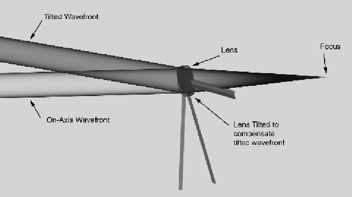
A single-lens corrector can be used effectively to control wavefront tilt by
moving it perpendicular to the optical axis and along the optical axis to correct for
defocus. Small motions of the lens does not introduce higher-order aberrations,
making this extremely effective. Also, the motion tolerances are reasonable. A sim-
plified single-lens corrector is shown in Fig. 4.5. A multiple-lens corrector can also
be used to correct tilt, but because of the additional DOF, it can be used to correct
higher-order modes as well.
Other optically powered devices can be used for active correctors, including
Fresnel zone plates.
Figure 4.5
Illustration of a single-lens tip-tilt corrector.