Environmental Engineering Reference
In-Depth Information
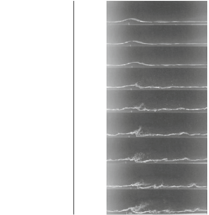
Fig. 11 Breakup at various
air velocities; constant mean
water velocity (0.676 m/s)
(Amano et al.
2014a
,
b
)
(a)
0 m/s
(b)
5 m/s
(c)
10 m/s
(d)
15 m/s
(e)
20 m/s
(f)
25 m/s
(g)
30 m/s
(h)
35 m/s
(i)
40 m/s
determined for the chamber inlet and outlet in terms of pixels after normalizing for
perspective distortion. The normalization was based on the constant chamber height
and center chamber height pixel reading.
The inlet water velocity was calculated using the volumetric
ow rate, chamber
depth, and measure approximate boundary height. The outlet water velocity, which
is the mean water velocity beneath the boundary surface, was calculated using high-
speed photography frames. The velocity was determined assuming mean velocity to
be similar to the observed entrapped air bubble velocity. Figure
12
shows the
fl
rst
and eighth frame used for the mean outlet velocity for the 40 m/s trial. The outlet
velocity is calculated by following the moving target for 0.01 m divided by the time
of the recorded frames.
Similar treatment as seen in Fig.
12
was given for air velocities of 10, 15, 20, and
30m/s. The water breakup ratios for these
flow rates were calculated and are presented
in Fig.
13
. The breakup ratio in percent form is the mass
fl
fl
flow rate of water when
leaving the chamber in two-phase
fl
flow relative to the inlet water mass
fl
ow rate.


Search WWH ::

Custom Search