Environmental Engineering Reference
In-Depth Information
been measured at a central location in the combustor, for certain sets of prede
ned
conditions. The corresponding
flame heights have also been analysed and compared
at these conditions. Based on the available data, an optimal level of premixing has
also decided upon in this study.
fl
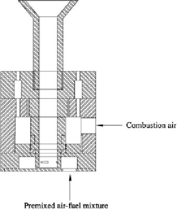
2 Experimental Setup and Procedure
The schematic diagrams of the burner con
guration and the experimental setup
have been shown in Figs.
1
and
2
, and a picture of the burner is shown in Fig.
3
.
The primary (premixing) and the secondary (diffusion) air are both taken from a
storage tank connected to an air compressor through separate lines. Both the air
ow
rates are measured using a rotameter each. The fuel is taken from a domestic LPG
tank and its
fl
flow rate is also measured using a rotameter. A pressure gauge is
provided to read the gauge pressure at the inlet of each rotameter. It is assumed that
there is no drop in the pressure across any of the rotameters, as the inlet valve is
completely opened for all the measurements. The
fl
flow rate is controlled using a
needle valve, one provided at the exit of each rotameter.
The premixing air and the fuel pass through the respective rotameters into a
premixing chamber, where they are thoroughly mixed. And from there, this pre-
mixed mixture is supplied to the burner. This premixed mixture comes out through
the centre of a
fl
fixed in
the centre of a perforated plate in the burner. There is a provision for tangential
swirling, through tangential slots cut at right angles at the bottom of the burner. The
premixed fuel
fl
flame holder, having diameter of the central tube as 10 mm;
air mixture enters the bottom of the burner, swirls through these
-
Fig. 1 Schematic of the
burner used in the experiment
Search WWH ::

Custom Search