Environmental Engineering Reference
In-Depth Information
guration is schematically shown in Fig.
5
.
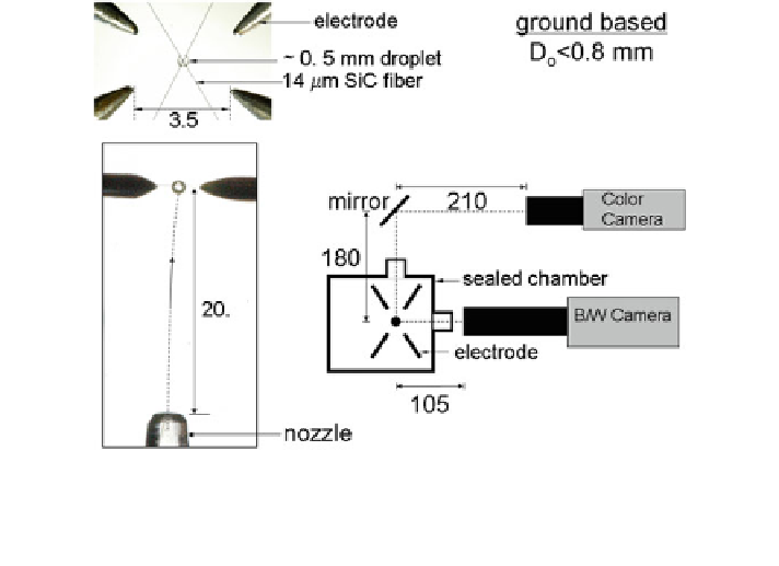
It involves deploying a test droplet at the vertex of two very small diameter
A small droplet experimental con
bers
crossed at an angle, essentially by propelling the test droplet onto the vertex with a
droplet generator (i.e., it is very dif
cult to deploy a droplet on the order of 0.5 mm
onto a 14-
m-diameter support structure by other methods). At that point, and after
the period of free fall begins, the droplet is then ignited by two sparks positioned on
opposite sides of the droplet to provide some degree of symmetry to the ignition
process. Digital video cameras record the burning history.
An unsupported droplet can be created using this same basic approach by
essentially removing the crossed
μ
fibers but still retaining the droplet trajectory. At
the apex of the trajectory, cameras positioned there, along with the sealed gas in
which the deployment process is carried out, are then literally released into free fall
(Okajima and Kumagai
1975
; Avedisian et al.
1988
). The downward motion of the
droplet falling at the same rate as the imaging system then creates the illusion of a
levitated droplet. Though creating unsupported droplets is very dif
cult, if suc-
cessful images like those shown in Fig.
4
b and c will result.
For large droplets, the multiuser droplet combustion apparatus (MDCA) is
designed to form and deploy unsupported or free-
oating droplets using the
approach schematically illustrated in Fig.
6
(Banu
2008
; Robbins and Shinn
2010
,
and Dietrich et al.
2014
).
fl
Fig. 5 Droplet deployment design for ground-based experiments (Liu et al.
2012
). Numbers are in
millimeters. Camera arrangement for recording the droplet burning history is shown. To create an
unsupported droplet, the 14-
m
fiber is removed and the sealed chamber is released into free fall
when the droplet reaches the apex of its approximately 20 mm deployment trajectory
μ
Search WWH ::

Custom Search