Environmental Engineering Reference
In-Depth Information
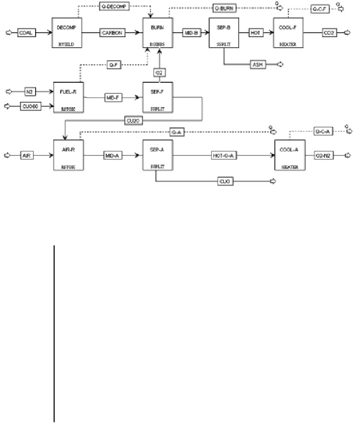
understanding the reaction equilibrium behavior. For Abad et al.
s experimental
setup (
2012
), we established an ASPEN Plus model as shown in Fig.
4
.
As summarized in Table
5
, coal devolatilization is de
'
ned by the RYIELD
reactor, followed by the gasi
cation of coal represented by the RGIBBS reactor.
The RSTOIC reactor de
nes the actual fuel combustion. It should be noted here that
these three reactor blocks together in Fig.
4
represent the fuel reactor in Abad
et al.
flow sheet within the ASPEN Plus simulation
package cannot model this entire reaction with one reactor. As a result, the fuel
reactor is broken down into several different reactor simulations. The air reactor is
modeled as an RSTOIC reactor. The molar
'
s experiments (
2012
). The
fl
fl
flow rate of CuO exiting and Cu
2
O
Fig. 4 Overall
fl
flow sheet of CLOU process in ASPEN Plus
Table 5 Process models used in different parts of CLOU process in ASPEN Plus
Name
Model
Function
Reaction formula
DECOMP
RYIELD
Coal devolatilization and
gasi
cation
Coal
→
volatile matter + char
BURN
RGIBBS
Syngas and char burn with
O
2
Char + volatile
matter + O
2
CO
2
+H
2
O
→
FUEL-R
RSTOIC
Carrier reduction reaction
4CuO
2Cu
2
O+O
2
→
AIR-R
RSTOIC
Carrier oxidation reaction
2Cu
2
O+O
2
→
4CuO
SEP-F
SSPLIT
O
2
and Cu
2
O Separation
*
SEP-A
SSPLIT
CuO and air Separation
*
SEP-B
SSPLIT
Separation
—
ash and
fl
ue
*
gas
COOL-F
HEATER
Flue gas cooler
—
fuel
reactor
H
2
O (gas)
→
H
2
O (liquid)
COOL-A
HEATER
Flue gas cooler
—
air reactor
*


Search WWH ::

Custom Search