Environmental Engineering Reference
In-Depth Information
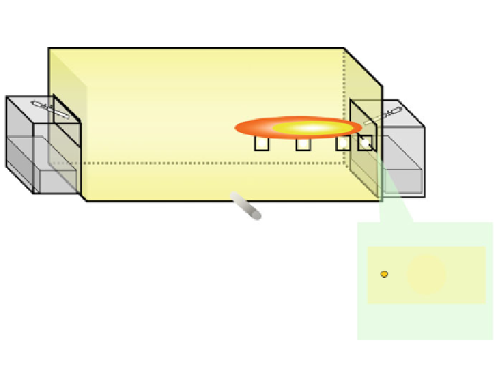
Thermal couples:(3
×
8)
8.0 m
2.0 m
2.0 m
Window
D
Window
C
Window
B
Window
A
Burner: A
Burner B
Exhaust duct
Fuel injector for
premixed combustion
Nitrous Oxide Analyzer
Air injector
Fuel injector for
diffusion combustion
Fig. 1 Schematic diagram of regenerative test furnace for steel slub preheating. Fuel: heavy oils
or natural gas
filters, merged again in the view
field of the video camera through another half mirror
after re
fl
ected. Either mirror was slightly tilted to separate the two-color images in the
view
field. Each pixel data obtained from the video camera was processed to obtain
temperature by post-numerical processing based on Eqs. (
1
) and (
2
).
3 Result and Discussion
Figures
3
and
4
show the one-shot pro
les of soot temperature observed through the
window A (upstream) and B (middle stream) during the premixedand diffusion
combustions, respectively.
It is clearly demonstrated in the
figure that during the premixed combustion the
high-temperature zone (shown in white) is observed around the left edge of
the window A. This high-temperature zone was found to be very steady, leading to
the high level of NO
x
emission over 120 ppm. Near the injector, premixed gas
undergoes very fast combustion reaction, leading to the high-temperature zone,
leading to high NO
x
emission.
On the other hand, the high-temperature zone is not encountered in the upstream,
during the diffusion combustion. It was found from a series of pro
le data that the


Search WWH ::

Custom Search