Environmental Engineering Reference
In-Depth Information
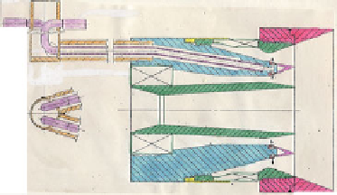
Radial
swirler
D=4”
Moderate swirl
Configuration 1/2
Weak Swirl
Configuration
3
Fuel nozzle with 3 swirlers ranging from weak
to moderate swirl strength; single or twin
rows of fuel jets in swirling cross streams.
Axial
swirler
Fig. 50 LDI-based combustor cross-section from Mongia (
2011b
)
swirlers) were tried; radial in
ow swirler closer to exit plane of the premixing tube
gave the best results. Typical air
fl
ow distribution at the simulated max-max power
(T
3
= 1158 K and P
3
= 490 kPa) is given in Fig.
51
along with its CO and NO
x
EI
characteristics in Fig.
52
. Two interesting observations need to be made here. First,
its NO
x
/P
0.5
value ranges between 0.6 and 1.5 EI/atm
0.5
which is very competitive
with the lowest values discussed earlier concerning Figs.
37
and
44
. Second, the
mixer survived during extensive rig testing at temperatures exceeding 1328 K with
the corresponding ignition delay times less than 0.2 ms even when the mixer may
be classi
fl
ed as a premixing and not LDI which we do not agree for the reasons
outlined in the following paragraph.
First, we used liquid fuel injection at the throat of two concentric venturis
involving both radially inward and outward directions normal to cross swirling
fl
flows, JIC. Second, two separate diverging concentric passages followed axially
downstream of JIC. This was followed by continuous fuel/air mixing in a single
diverging passage until the radial swirler. The swirl strength of the three concentric
swirlers was optimized, which starting from center increased from very weak
(
) for the outer-mounted
injector swirler, as shown in Figs.
49
and
50
. The point of disagreement could be
≤
15
°
),
to weak (
≤
30
°
), and moderately strong (
≤
45
°
Fig. 51 Air
fl
flow distribution of the mixer configuration tested at
the simulated max-max
operating point; from Mongia (
2011b
)


Search WWH ::

Custom Search