Environmental Engineering Reference
In-Depth Information
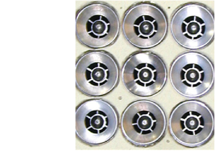
Fig. 42 The baseline 9-point
SV-LDI design; from Tacina
et al. (
2005a
)
cross-section of 76.2 mm
76.2 mm. Tacina et al. (
2005a
) summarize test results
with three different helical vane angles, viz. 45
×
°
, 52.5
°
, and 60
°
showing advantage
of the 45
swirlers for lower NO
x
but limited by operability range. The measured
effective area of this module was 955 mm
2
giving a combustor area expansion ratio
of 6.1, a design parameter of great signi
°
cance.
The second generation SV-LDI (LDI-2) comprises of a
“
”
surrounded by 12
main/intermediate (M) fuel/air mixers for a combustor of 114.3 mm
pilot
114.3 mm
square cross-section. The M mixers were divided into three discrete groups of four
identical mixers identi
×
ed as m
1
, m
2
, and m
3
(Fig.
43
) in two very different
arrangements. The con
guration on the left (to be called
fl
at dome LDI-2) has
classical fuel staging pattern used in diffusion
fl
flame annular combustors (viz. Bruce
et al.
1977
), namely alternately
flowing fuel nozzle at idle with attendant reduction
in lean blowout fuel/air ratio (LBO FAR), CO, and hydrocarbons (HC). The con-
fl
figuration on the right has also a classical fuel staging pattern called sector burning
involving alternate pairs of
flowing nozzles which might lead to further reduction in
idle LBO FAR, CO, and HC. However, in order to further improve its operability
characteristics, the con
fl
guration on the right has both the pilot and the m
1
mixers
recessed relative to the m
2
and m
3
mixers; and therefore called recessed LDI-2. As
summarized in Table
6
,
counter
clockwise (CCW) with a longer increased exit diameter diverging section and
pressure atomizer was designed to give higher low-power stability. However, m
1
mixers have 45
0
vane angles in order to get lower NO
x
, but with simplex pressure
atomizers for providing good ignition source for both the m
2
and m
3
mixers. The
the baseline pilot
'
s swirl vane angle of 55
°
Search WWH ::

Custom Search