Environmental Engineering Reference
In-Depth Information
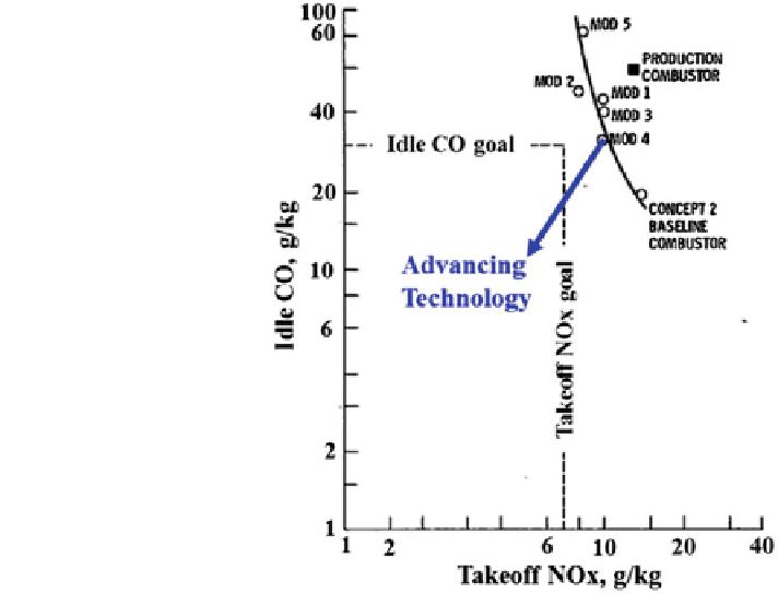
Fig. 7 A typical example of
idle CO versus takeoff NO
x
tradeoff in low-emissions
combustion technology;
adopted from Fear (
1976
)
years including the co-rotating axial swirlers for the CF6-50 reported by Bahr and
Gleason (
1975
), Fig.
3
. The
five major subcomponents of swirl cups (viz. injector,
venturi,
gured in several
ways (Figs.
3
,
4
and
5
) in order to achieve the design objective; and the similar
statement is perhaps applicable to another equally innovative mixer shown in Fig.
6
.
Any initial successful demonstration of a particular mixer is followed by its own
set of optimum aerothermal-mechanical design features for the rest of the combustor
(viz. dome, combustor liner, air
fl
flare, primary, and secondary swirlers) have been con
ow distribution, and attendant geometrical features)
guided by experience, CFD, rig and engine testing leading to
fl
final certi
ed products
that must meet the combustion system requirements brie
fl
y described in Sect.
2.2
.
2.2 Design Requirements
Table
1
gives a partial list of super-system level requirements from a typical avi-
ation engine expected from the combustion system; which in practice runs into a
design requirement document containing several pages with quantitative details
which can vary with different applications. These requirements translate into
combustion system level design requirements (Table
2
) to be used as a guide across
several interdependent disciplines including aero, heat transfer (thermal), mechan-
ical, materials, manufacturing, controls and accessories, CA
2
TM
3
—
or simply
Search WWH ::

Custom Search