Geometry comes in a few different flavors. Maya can be used to create NURBS, polygonal, and subdivision surface geometry. Each has its own particular strengths t7T*J and weaknesses; learning to use all three types is important. Here’s a broad oversimplification that’ll get a bunch of people all worked up.
• NURBS are good for creating organic squishy objects.
• Polygons are good for hard-edged, man-made objects.
• Subdivision surfaces are good for everything.
OK, that said, let’s take a closer look.
NURBS
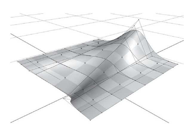
NURBS stands for Non-Uniform Rational B-Spline. Unless you are on CG Mathematician Jeopardy, you’ll never need to know what that means. The important part is that NURBS curves and surfaces can be a good way to create organic models (see Figure 2.6). NURBS models are resolution independent (sort of like the vector graphics in Illustrator and Flash), which means your surfaces are defined mathematically to look good when rendered, no matter how close your camera gets.
All renderers in wide use today, including Maya’s native render engine, must convert your geometry to polygons right as they begin rendering. So why don’t you see telltale polygonal facets? The trick involved here is that the sphere, for example, is described by the NURBS surface parameters as being perfectly round. When the scene is rendered, Maya can use as many facets as necessary to make the surface appear smooth.
Polygons
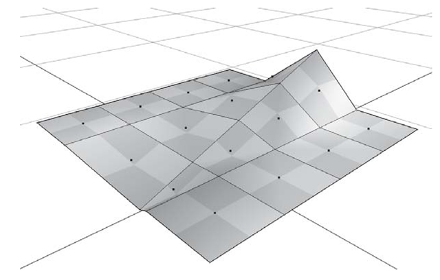
Polygonal geometry is made up of facets - called faces. These three-sided polygonal faces are the result of connecting the dots of three points – called vertices. The lines used to connect each vertex are called edges (see Figure 2.7). Polygonal geometry can be great for creating hard surfaces like buildings and machines, or if you use enough polygons, organic characters and props.
Unlike NURBS surfaces, polygonal geometry doesn’t easily adapt its resolution to remain smooth looking in close-ups. Polygonal objects are made of a finite number of facets regardless of proximity to the camera. But polygons can be quicker to render as a result. And polygonal objects can support branching topography (such as fingers or spokes), with which NURBS surfaces have a hard time.
Subdivision Surfaces
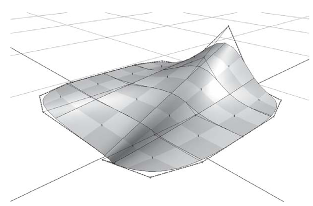
Subdivision surface objects act as a sort of hybrid between the other two surface types (see Figure 2.8). They are resolution independent, like NURBS, and yet they allow arbitrary topology, like polygons. They are the bee’s knees. With sub-d objects it is possible to add localized detail where you need it, punch holes through the surface, and define hard creases and smooth curves in the same model.
Figure 2.6: NURBS surface
Figure 2.7: Polygon surface
Figure 2.8: Subdivision surface
Component Mode
Components are the parts that lie just below the object level of a model. At the component level you’ll find the points, lines, and surfaces that make up the model (see Figure 2.9).
Points can be used to create a new shape, sort of like pushing and pulling clay. A NURBS point is called a control vertex, or CV. A polygonal and subdivision surface point is a vertex.
Lines connect the points. A NURBS line that lies directly on the surface is called an isoparm. (NURBS points are connected with hulls.) A polygonal and subdivision surface line is called an edge.
When the points and lines are doing their job, you’ll end up with a surface. A NURBS surface is called a patch. The polygonal and subdivision surface equivalent is called a face.
Use the Status Bar component icons to pick these different components. Alternately, press F8 on your keyboard to switch into component mode.
Figure 2.9: Geometry components
Modeling Exercise — NURBS Components
1. Set your project to understanding_maya\Chapter02\modeling_icecream.
2. Open the scene modeling_icecream_begin.ma.
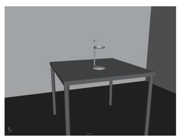
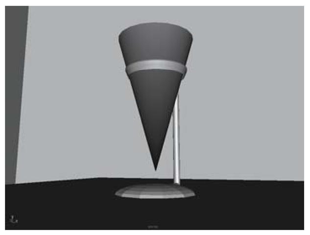
3. You will see the familiar room and table, but this time there is a small stand on the table (see Figure 2.10). You will be modeling an ice cream cone, some ice cream, and a cherry.
4. First, click on Create > Polygon Primitives > Cone to create the cone. Rename this object waffleCone.
5. Dolly out so you can see the cone. Use the Move Tool to place the cone in the middle of the stand, about 0, 12.5, -5 on translate X, Y, and Z.
6. Next, use the Rotate Tool to flip the cone around 180 degrees on the Z-axis.
7. Use the Scale Tool to elongate the cone, about a factor of 1.75 units on the Y-axis (see Figure 2.11).
8. For the remainder of the exercise, be sure that the Construction History button is in the On position. You can check this in the Status Line. The Off state has a red X going through it.
9. Create a NURBS sphere. Rename it Scoop.
Figure 2.10: Initial scene
Figure 2.11: Added cone
10. Translate the Scoop to 0, 14.5, -5.
11. In the Channel Box, look for the INPUTS node. Click on the word makeNurbsSphere1. This opens up the list of input channels for the Scoop.
12. Increase the number of Sections to 10, and the number of Spans to 6. You will see the number of Isoparms increase on the Scoop. This extra geometry will be needed in order to reshape the ice cream — the more detail you want in a surface, the more geometry it’ll require.
13. The standard mode of selection in Maya is called Object Mode. All of your picking occurs on the object level, such as lights, surfaces, and cameras. When you want to select components, such as the Control Vertices (CVs), edges, and faces of an object, you must choose Component Mode. To switch to component mode, click on the Select By Component Type button in the status line.
14. Make sure that the Points component type is selected. This is the square point icon just after the Select By Component Type button.
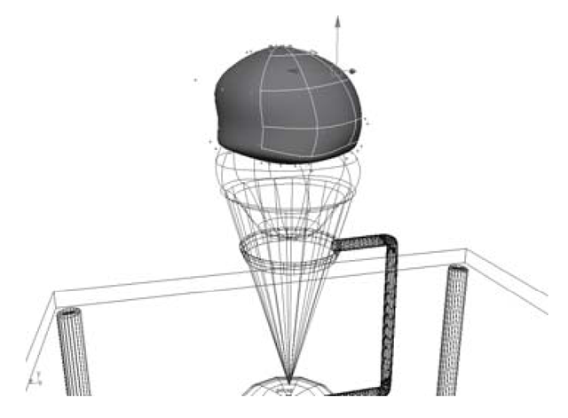
15. The CVs for the Scoop are now displayed and can be selected and translated. Try picking and then using the Move Tool on CVs or whole rows of CVs. Reposition them to form a more natural-looking ice cream scoop (see Figure 2.12).
16. One way to get even-looking shape transformations is to marquee select entire rows of CVs and then use the Scale Tool on them. This has the effect of pushing all of the selected CVs away from each other, or pulling them in toward the selection’s center.
17. The Rotate Tool can also be used to make a broad change to a selection of CVs.
Figure 2.12: The reshaped sphere scoop
Figure 2.13: The second scoop
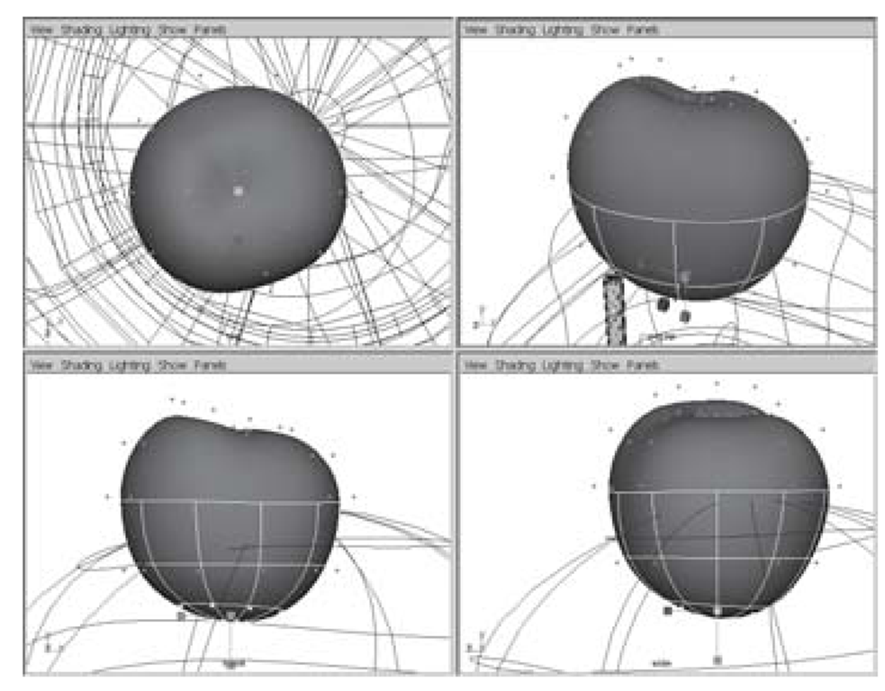
18. Be sure to check the top, front, side, and perspective camera views when sculpting a surface.
19. When you are satisfied with the shape of the Scoop, return to object mode. You can click the Select By Object Type button on the status line, or press F8 to toggle between object and component pick masks.
20. Repeat steps 8 through 18 in order to make a second scoop named Scoop02. This scoop should be translated higher on the Y-axis so that it sits on top of the first one (see Figure 2.13).
21. Using the same techniques as the ice cream scoops, model a cherry for the top of the scoops. We will do the stem separately, so just create the cherry itself for now (see Figure 2.14). Name it Cherry.
22. For the stem, create a NURBS cylinder, and name it Stem.
23. Translate and scale the Stem into position above the Cherry. (Try scale 0.035, 0.5, 0.035 if you want a general guideline.)
24. In the INPUTS node of the Channel Box for the Stem, click on the word makeNurbCylinder1. Increase the number of Spans to eight.
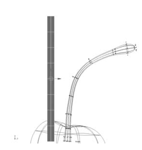
25. With the Stem selected, toggle to Component Mode (F8) and sculpt the stem using the Move, Rotate, and Scale Tools on the CVs (see Figure 2.15).
Figure 2.14: Modeling the cherry
Figure 2.15: From cylinder to stem
26. Now, let’s create some materials to apply to the cone, scoops, cherry, and stem. Click on the Quick View button for Hypershade/Persp. In the Hypershade menu, click Create > Materials > Phong.
27. Since you’ll be editing the attributes of a number of materials, it’s helpful to “dock” the Attribute Editor into the interface. A floating window can get in the way if you are using it a lot. To dock the Attribute Editor, click the Show or hide the Attribute Editor button in the status line. This takes the place of the Channel Box/Layer Editor.
28. Change the name of the newly created Phong material to phongCone.
29. Change the Color attribute to a yellow/orange color (HSV 47, 0.9, 0.9).
30. Decrease the Cosine Power to 7 — this has the effect of broadening the specular highlights of the material, making it look less like plastic.
31. Drag the Specular Color slider to the left, to about the one-quarter position. This decreases the brightness of specular highlights, dulling the material.
32. MMB-drag the phongCone material onto the waffleCone object.
33. Create another Phong material. Name it phongVanilla.
34. Change the Color to slightly off-white.
35. Increase the Ambient Color slider slightly.
36. Set the Cosine Power to 16.
37. Lower the Specular Color to about the one-quarter position.
38. MMB-drag thephongVanilla material onto the Scoop object.
39. In the Hypershade, select the phongVanilla material, click Edit > Duplicate > Shading Network. This makes a copy called phongVanilla1. Rename it phongChocolate.
40. Change the phongChocolate color to brown (HSV 27, 0.65, 0.4).
41. MMB-drag phongChocolate onto the Scoop02 object.
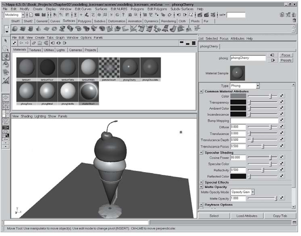
42. For the cherry, create a new Phong material, and name it phongCherry.
43. Change the color to deep red (HSV 3, 0.9, 0.8)
44. For a tight highlight, increase the Cosine Power to 80.
45. Change the Specular Color to a light grey, about three-quarters to the right on the slider.
46. MMB-drag thephongCherry material onto the Cherry and Stem objects (see Figure 2.16).
47. Save the scene as modeling_icecream_end.ma.
Figure 2.16: The finished model
