Modeling Exercise — Lofting Curves: Slide
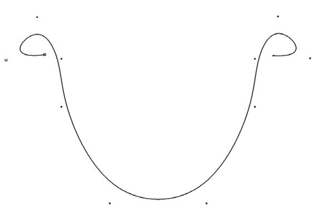
1. In the front view, use the CV Curve Tool to create a curve in the shape of a water slide’s cross-section. Make the curve about six units wide and four units tall (see Figure 3.24).
Figure 3.24: Loft profile curve
2. Notice how the curve’s pivot point is at the world origin (0,0,0) regardless of where you drew it on screen. Just to make things easier to transform later, we’ll center the curve’s pivot point by selecting the curve, and then clicking Modify > Center Pivot.
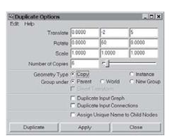
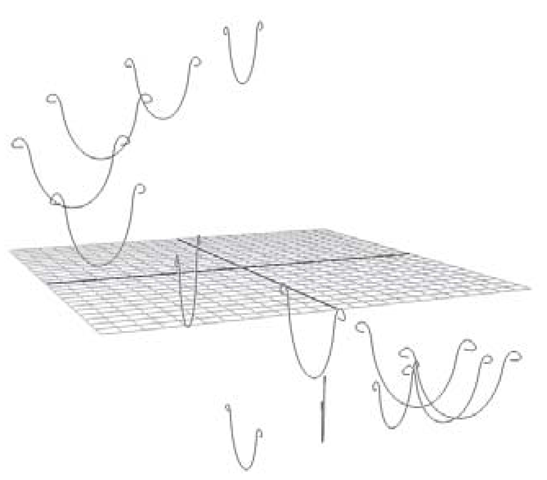
3. Lofts are created from a series of curves. You’ll generate a better loft when those curves have the same number of points and are drawn in the same order (left to right, for example) as each other. This is a good time to use the Duplicate command. With the curve selected, click Edit > Duplicate options. In the Duplicate Options window, click Edit > Reset Settings, to get back to the defaults. Now, we’ll tell each successive curve to be moved out on the Z-axis and down on the Y-axis, all while rotating a bit. Try these settings: Translate: 0, -2, 5; Rotate: 0, 30, 0; and Number of Copies: 12. Click the Duplicate button (see Figures 3.25 and 3.26).
4. Since the number of copies (12) multiplied by the angle of rotation (30°) is equal to 360°, the duplicated curves form a complete spiral. Select all of the curves in the Outliner, starting with curve1, and then shift-clicking on curve13. (In the next exercise we’ll explore how curve selection order will affect the type of lofted surfaces you create.)
Figure 3.25: Duplication options
Figure 3.26: Loft profiles
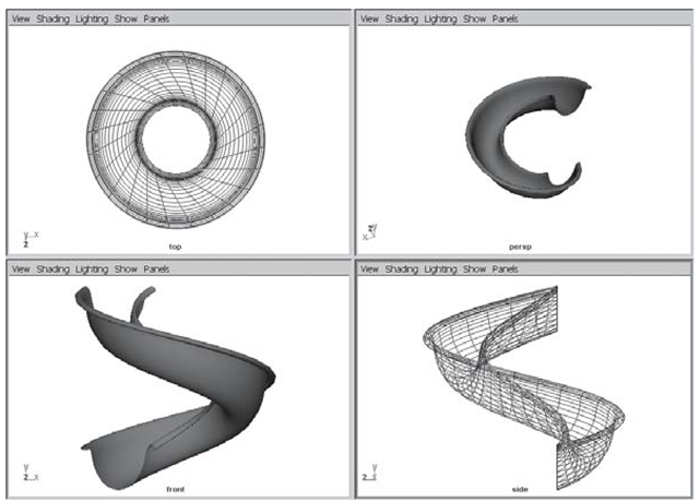
5. In the Modeling Menu Set, click Surfaces > Loft options. Reset the settings, and then click the Loft button. This will make a single surface that is stretched across all of your profile curves (see Figure 3.27).
Figure 3.27: Lofted surface
Modeling Exercise — Lofting Curves: Fish
1. In this exercise we’ll take a look at how the selection order of your profile curves affects lofted surfaces. Set your project to understanding_maya\Chapter03\modeling_lofting.
Figure 3.28: Loft curves
2. Open the scene lofting_order_fish_begin.ma.
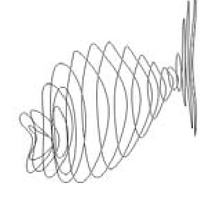
3. You’ll see a series of NURBS curves in the scene (see Figure 3..28). They have been shaped to form the outline of a fish. In order to build the surface of the fish model, you’ll want to select the curves and then perform a loft. As you’ll see, the order in which you select the curves affects the outcome of the loft command.
4. In the perspective panel, select all the curves by LMB-click-dragging a marquee around the entire set of curves.
5. With your curves selected, click on Surfaces > Loft options.
6. Just to be sure you’re using the default settings, click Edit > Reset Settings in the Loft Options menu, then click the Loft button.
7. You should see a strange looking, inside-out fish! Click 3 on the keyboard while the new loftedSurface1 object is selected. This will place it into fine smoothness mode (see Figure 3.29).
So what happened here? Why is this fish so darned ugly? As it turns out, the marquee selection we used to pick the curves was not specific enough to create a predictable lofted surface. Maya always lofts curves in the order in which they were selected. By starting out with a vague selection order (the marquee selection picks objects in the same order as their original creation) the loft is not what we expected.
Figure 3.29: Incorrect loft order
8. Delete the poor mangled fish so we can start over again by selecting the loftedSurface1 object and pressing Delete on your keyboard. Be careful not to delete any curves.
9. This time, we’ll try to be a bit more specific about selection order. Switch to your side panel by RMB-clicking on it. Then maximize the side panel by tapping the Spacebar.
10. While holding the Shift key to make a multiple selection, click on each curve starting from the far left and heading to the far right of the screen. You’ll notice each curve turn white, except for the final selection, which turns green.
11. Again, generate the surface by clicking Surfaces > Loft.
12. Well, this fish is looking a little healthier, but still has some issues (see Figure 3.30). Press 3 to see the smooth representation of the surface. You’ll notice that a strict sequential selection of curves made for some problems in the head and mouth area.
Figure 3.30: Ugly fish
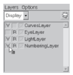
Figure 3.31: Layers
13. Delete this unfortunate freak of nature (loftedSurfacei) so we can try one final time.
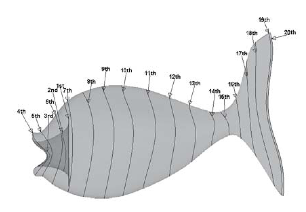
14. There is a very specific order of selection that will work for these curves. To see the order numbered on-screen, turn on the visibility of the NumbenngLayer in the Layer Editor, by clicking the empty box at the far left of the layer (see Figure 3.31). It will turn to a “V” when clicked and you’ll see a set of number annotations appear in the modeling views.
15. Maximize your side panel so you can clearly see the order of curve selections. Using the Shift selection technique, click each curve from the first through the twentieth.
16. Create the surface by clicking Surfaces > Loft.
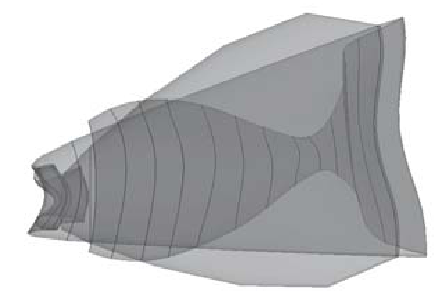
17. A much happier fish! Go ahead and increase the display smoothness and take a look at the model in the perspective panel. Hit 5 on your keyboard to turn on hardware shading mode. To really see what’s going on, it can be helpful to make the surface partially transparent (see Figure 3.32). In your perspective panel menu, click Shading > Shade
Figure 3.32: X-ray mode Options > X-Ray.
Now you can see a bit more clearly how the curve order has been used to create the loft. Look at curves one through eight. Notice how we start with a medium-sized curve set inside the fish’s interior, and then move toward the front of the mouth with curves two and three. Curves four, five, and six help define the protrusion of the mouth and then flow toward the head.
18. Let’s add a couple of finishing details. First, turn off the perspective panel’s X-Ray mode. (Shading > Shade Options > X-Ray.) Next, hide the numbers and curves by turning the visibility off on the NumbermgLayer and CurvesLayer.
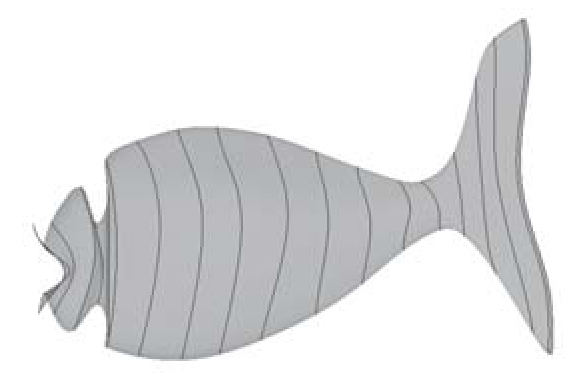
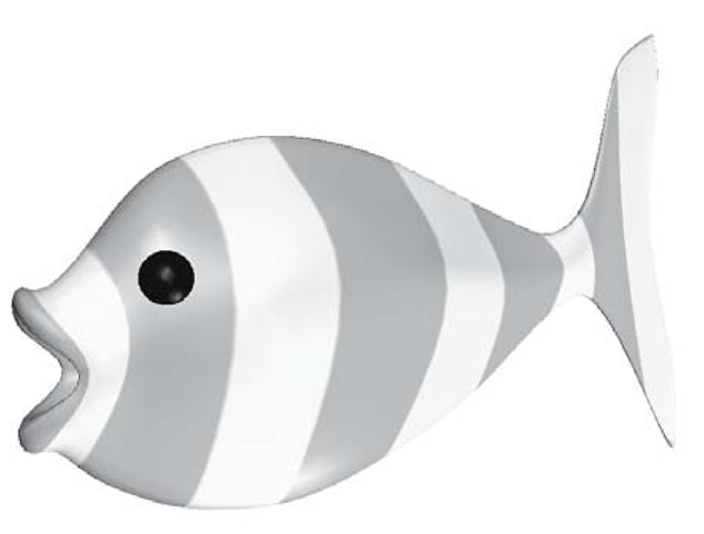
19. Rename the loftedSurface1 object, calling it fish. RMB-click on the fish object and choose from the marking menu Materials > Assign Existing Material > Fishphong. To see the texture, turn on hardware texturing by pressing 6 on your keyboard. You can also turn on the visibility for the EyeLayer (see Figure 3.33).
20. Save your scene as lofting_order_fish_end.ma.
Figure 3.33: Final fish
